3D Workspace
Home
Assets
Affiliate Program
Creator Program
Sign up/Log in
?
Upgrade
DCC Bridge
Anonymous1758655626
04-08 21:46
Model Name
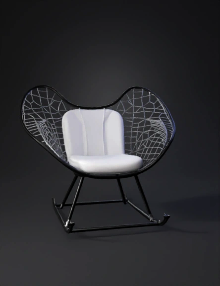
wire chair 3d model
Tags
furniture
furniture realistic
furniture rendering
furniture rendering realistic
realistic
rendering
rendering realistic
wire chair
Prompt
Imagine a wide, sculpted armchair where the seat and backrest are formed from a single, continuous, highly contoured metal shell. This shell is entirely constructed from steel wire. The Shell Form: The shape is a complex, double-curvature surface—scooping downward to form a deep seat, sweeping upward and backward to support the spine, and flaring out widely at the top shoulders, resembling a bird's wings in flight. It is organic; there are no perfectly flat planes. The Wire Grid: The outer edge is defined by a heavy, continuous perimeter wire. Inside this frame is a lattice of thinner wires (the video states there are 62 rods in total). These wires do not form a standard square grid; instead, they run diagonally to form a diamond or crisscross pattern. Every single intersection where one wire crosses another is spot-welded. The Base & Suspension: The wire shell does not touch the ground directly. It rests on a separate, minimalist base made of thicker steel rods bent into an angular "sled" configuration. The Connection Points: The shell is attached to the base using four heavy-duty cylindrical rubber shock mounts (bushings). These rubber cylinders act as a suspension system. They are bolted to tabs on the base frame and welded to the wire shell, allowing the rigid wire cage to flex slightly when a person sits, preventing the welds from snapping under dynamic loads. Upholstery: A tailored, padded fabric cover is slipped over the front of the wire shell. It hooks over the thick perimeter wire, cushioning the body while leaving the intricate wire lattice visible from behind. Part 2: Automation & Motor Control Strategy You asked how to control your motorized screw-rods to form this shape "by just showing a video." You cannot feed video pixels directly to motor drivers; you must bridge the gap between 2D optical data and 3D mechanical coordinates. If treating your motorized screw-rod setup as a custom Cartesian robot, here is the data pipeline: Extract the 3D Point Cloud: Use photogrammetry software. By feeding the software multiple frames from a video panning around the chair, it will calculate depth and generate a 3D point cloud of the wire intersections. Surface Reconstruction (CAD): Import that point cloud into a CAD environment (like Rhino/Grasshopper or SolidWorks) to fit a smooth NURBS surface over the points. Node Extraction: Isolate the exact X, Y, Z coordinates of every wire intersection on that curved surface. Kinematics & Toolpath Generation: Write a Python script to translate those 3D coordinates into G-code. Your controller (e.g., a PLC or a Raspberry Pi) will process this G-code, applying the inverse kinematics of your specific screw-rod geometry to calculate the precise step counts required for your stepper/servo motors to move the spot-welding heads into position.
Detailed Info
Related Models
Enter invite code
Enter invite code to get credits!
 Anonymous1758655626


 Anonymous1758655626