3D Workspace
Home
Assets
Affiliate Program
Creator Program
Sign up/Log in
View Plans
DCC Bridge
venevarsh
12-18 06:04
Model Name
futuristic machine 3d model
Tags
electrodes
futuristic machine
machine
machine realistic
machine rendering
machine rendering realistic
realistic
rendering
rendering realistic
semiconductor
Prompt
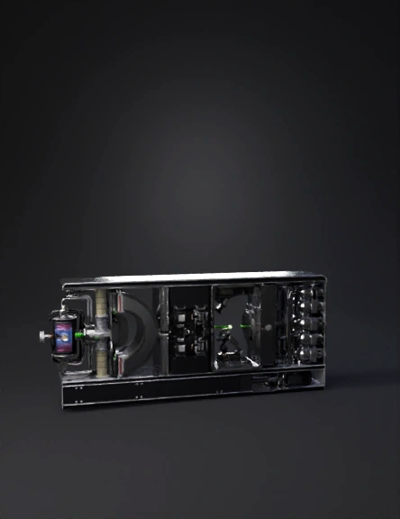
Inside Working of an Ion Implantation Machine (Semiconductor Fabrication – Correct Technical Description) An ion implantation system introduces controlled dopant atoms (such as boron, phosphorus, or arsenic) into a silicon wafer by accelerating ions at high energy and embedding them into the crystal lattice. The tool operates under high vacuum and is divided into six main internal subsystems, arranged linearly. 1. Ion Source Chamber Function: Generate charged dopant ions Dopant gas (BF₃, PH₃, AsH₃) or solid source is introduced RF or arc discharge ionizes the gas Produces positive ions (B⁺, P⁺, As⁺) Operates at low pressure (~10⁻⁴ Torr) 3D elements to model: Plasma chamber RF coils or arc electrodes Gas inlet lines Extraction aperture 2. Extraction & Acceleration Column Function: Pull ions out and accelerate them Electrostatic extraction electrodes pull ions from plasma High voltage (10 keV – 3 MeV depending on tool) Defines ion energy → determines implant depth Key concept: Energy = penetration depth 3D elements: Extraction grids High-voltage insulators Acceleration tube Shielded column housing 3. Mass Analyzer (Magnetic Sector) Function: Select only the correct ion species Uses a strong magnetic field Ions bend based on mass-to-charge ratio Unwanted ions are physically blocked Example: B⁺ passes BF₂⁺, F⁺ are rejected 3D elements: Curved beam path Large electromagnet Ion dump plates Beam aperture slit 4. Beam Transport & Beamline Optics Function: Shape, focus, and steer the ion beam Electrostatic lenses focus the beam Scanning plates sweep beam uniformly Beam current monitors ensure dose accuracy Why needed: Ensures uniform dopant concentration across wafer 3D elements: Quadrupole lenses Deflection plates Faraday cups Beam diagnostics sensors 5. End Station (Wafer Chamber) Function: Implant ions into wafers Wafers loaded via FOUP or cassette Chuck holds wafer (electrostatic or mechanical) Wafer rotates and tilts for uniformity Temperature controlled (room temp or heated) Ion beam hits wafer → ions embed into silicon 3D elements: Wafer chuck Rotation mechanism Tilt stage (7° typical to reduce channeling) Shielded chamber walls 6. Vacuum & Exhaust System Function: Maintain ultra-clean environment Turbo molecular pumps Cryo pumps Roughing pumps Prevent contamination and scattering Operating pressure: ~10⁻⁶ to 10⁻⁷ Torr 3D elements: Pump stacks Vacuum lines Gate valves Pressure gauges Complete Working Sequence (Step-by-Step) Dopant gas enters ion source Plasma ionizes dopant atoms Ions extracted and accelerated Magnetic analyzer selects correct ion Beam focused and scanned Ions strike wafer surface Dopants embed at controlled depth Wafer unloaded → annealing follows later What Your 3D Model MUST Show For technical correctness, include: ✅ Linear beam path ✅ Magnetic mass analyzer bend ✅ High-voltage acceleration column ✅ Rotating wafer chuck ✅ Large vacuum pumps ✅ Shielded metal enclosures Common Mistakes to Avoid in 3D Models ❌ No magnetic analyzer ❌ No beam bending ❌ Atmospheric pressure chamber ❌ Ions sprayed randomly (they must be collimated) ❌ No vacuum pumps
Detailed Info
Related Models
Enter invite code
Enter invite code to get credits!