3D Workspace
Home
Assets
Affiliate Program
Creator Program
Sign up/Log in
View Plans
DCC Bridge
vicky2006sv
11-20 06:57
Model Name
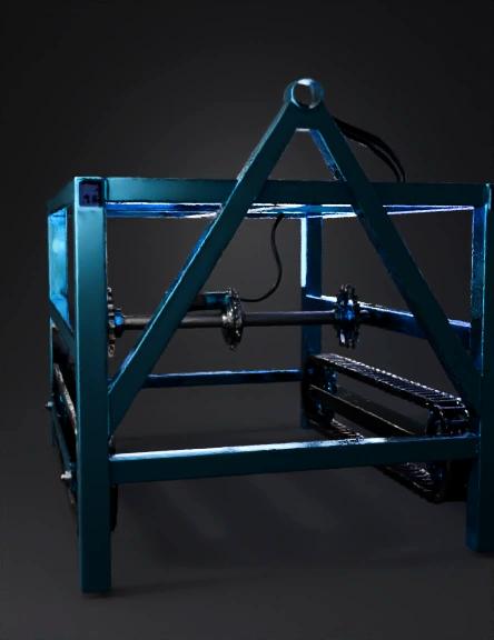
chain-driven tracked frame 3d model
Tags
frame structure
machine
machine realistic
machine rendering
machine rendering realistic
realistic
rendering
rendering realistic
Prompt
Model: Chain-Driven Multi-Leg Agricultural/Robot Vehicle Frame Your model is built using a combination of rectangular iron rods, chain–sprocket wheel mechanism, and supporting vertical legs. The design resembles a miniature tracked vehicle (like Hitachi earthmovers), combined with a walking stabilizer frame. --- 🧱 1. FRAME STRUCTURE (IRON RODS USED) The entire structure is made completely from rectangular hollow steel rods (square metal tubing). From the images, the vehicle contains: --- ✅ A. Top Frame – 4 rods This forms the upper rectangular box. It consists of: 1. Front horizontal rod 2. Rear horizontal rod 3. Left side horizontal rod 4. Right side horizontal rod These 4 rods form a rectangle. On top of this rectangle, your plywood platform or electronics board is mounted. --- ✅ B. Middle Support Rods – 2 rods Inside the top rectangle, two more rods are welded: 5. Central cross support rod 6. Back cross support rod These rods strengthen the frame and hold the motor/sprocket mechanism. --- ✅ C. Front A-Frame Support – 2 rods There is a triangular “A-shape” frame in the front. 7. Left slanted support rod 8. Right slanted support rod These two rods rise from the sides and meet at the top, creating a triangular frame. This provides high structural rigidity, similar to a crane or excavator frame. --- ✅ D. Vertical Support Legs – 4 rods At each corner, a vertical iron rod is welded: 9. Front left vertical rod 10. Front right vertical rod 11. Rear left vertical rod 12. Rear right vertical rod Each vertical rod supports the track assembly and stabilizes the vehicle. --- ✅ E. Side Horizontal Base Rods – 2 rods These rods connect left and right legs at the bottom: 13. Left side bottom connector rod 14. Right side bottom connector rod These rods hold the sprockets and chains. --- ✅ F. Track Chain Frame Rods – 4 rods (2 per side) Each side has a chain-supporting frame: Right Side: 15. Upper chain supporting rod 16. Lower chain supporting rod Left Side: 17. Upper chain supporting rod 18. Lower chain supporting rod These four rods hold the sprockets that drive the chain track. --- 🔢 TOTAL IRON RODS = 18 --- 🚜 2. TRACK SYSTEM (LIKE HITACHI TRACK VEHICLE) Your machine uses a miniature tracked-wheel mechanism, similar to excavators (Hitachi, JCB, CAT machines). --- 🔗 A. Side Chain Mechanism (Both Sides) Each side contains: A continuous roller chain Attached track plates (small rectangular metal plates) Three sprockets on each side So total: 2 chain loops (one on each side) 6 sprockets (3 right + 3 left) --- 🛞 B. Sprocket Positions (per side) Each side shows 3 sprockets: 1. Front Bottom sprocket – placed near the vertical leg 2. Rear Bottom sprocket – supports rear 3. Top center sprocket – gives tension and aligns the chain This exact mechanism is used in: Hitachi tracked excavators Bulldozers Tracked agricultural robots Function: Bottom sprockets carry load Upper sprocket tensions chain Chain continuously rotates like a tank --- 🦾 3. HOW THE TRACK PLATES ARE ATTACHED On the chain, small rectangular steel plates are welded at intervals. These plates act as: Track shoes (like excavator shoes) Provide traction Prevent slipping Help the machine move on soil, mud, or uneven surfaces --- ⚙ 4. CENTRAL MECHANISM (MOTOR & CHAIN DRIVE) Inside the frame (visible from top): There are two wires, indicating the motor placement Motor will rotate the main sprocket shaft The shaft rotates both left and right track chains simultaneously This ensures: Straight movement Equal torque distribution Stability --- 🧱 5. COMPLETE STRUCTURE EXPLANATION (BIGGEST DESCRIPTION) This vehicle is built using a rectangular chassis made from 18 iron rods. The top 4 rods create the main frame, inside which 2 additional rods give support. The front triangular A-frame uses 2 rods that provide rigidity for motor mounting or additional mechanisms. Four vertical rods act as legs, holding the bottom structure. Two more horizontal rods at the bottom connect these legs and serve as mounting beams for the chain drive. Each side has a two-level frame (upper and lower rods), holding three sprockets forming a triangular chain path. The chain runs in a loop around these sprockets, with small rectangular plates attached, forming a miniature excavator track system. When the motor rotates the central drive sprocket, both chain loops rotate, enabling vehicle movement. The structure resembles a compact tracked robot or a small agricultural automation machine with the stability and functionality of Hitachi-style tracked vehicles.
Detailed Info
Related Models
Enter invite code
Enter invite code to get credits!