3D Workspace
Home
Assets
Affiliate Program
Sign up/Log in
?
Upgrade
DCC Bridge
Anonymous1771280548
02-20 19:17
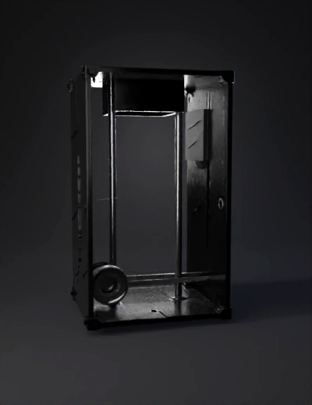
Model Name
分光计部件3d模型
Tags
3d printing
3d printing realistic
machine
machine 3d printing
machine 3d printing realistic
machine realistic
realistic
spectrometer
Prompt
Model this individually: # 🔷 I. COMPLETE LIST OF SPECTROMETER PARTS ## 🧩 A. External structure 1. Main spectrometer body (lower housing) 2. Removable top cover 3. Front input plate (1.25” interface) 4. 1.25” cylindrical adapter (barrel) 5. Rear closing plate 6. Longitudinal internal structural support (optical rail) 7. Mounting system to an external base (lower bracket) --- ## 🔬 B. Optical system 8. Slit holder 9. 0.3 mm slit 10. Transmissive grating holder frame 11. Transmissive diffraction grating 12. C-mount lens holder 13. C-mount lens 14. Camera support plate 15. OV2640 camera --- ## 🔩 C. Fastening and alignment components 16. Internal alignment spacers 17. M2 threaded posts for the camera 18. M2 screws for the camera 19. M3 screws for the internal structure 20. M4 or M5 screws for the housing 21. Rear cable slot or cable gland --- ## 🔌 D. Cable management 22. Internal channel for the FPC cable 23. Rear exit hole Ø12 mm 24. Rear cover with cable slot --- # 🔷 II. DETAILED TECHNICAL DESCRIPTION, PART BY PART Now I will describe each part as if it were an engineering specification for parametric modeling. --- # 1️⃣ MAIN SPECTROMETER BODY (Lower housing) This part is a hollow rectangular block designed to house the internal optical system. Its external dimensions must be: L Overall length: 120 mm W External width: 60 mm H External height: 60 mm Wall thickness: 4 mm The part must be modeled as a solid rectangular block of 120×60×60 mm and then hollowed out internally, leaving uniform 4 mm walls on all sides. The interior must have usable dimensions of: 112 mm internal length 52 mm internal width 52 mm internal height Inside, there must be a centered longitudinal guide, 10 mm wide and 5 mm high, running along the optical axis to secure the internal supports. The front side must include a centered circular seat of Ø32 mm to receive the front plate. --- # 2️⃣ TOP COVER Rectangular plate: 120 mm length 60 mm width 4 mm thickness It must include 4 corner holes for M4 screws, offset 8 mm from each edge. It must include a recessed perimeter groove, 1 mm deep and 3 mm wide, for a hermetic seal. --- # 3️⃣ FRONT INPUT PLATE This is a square plate: 60 mm × 60 mm 6 mm thickness At the center it must have a through hole of Ø31.8 mm for the 1.25” barrel. It must include 4 M4 holes in a square pattern with 45 mm center-to-center spacing. The inner side must have a circular recess of Ø40 mm and 3 mm depth to seat the adapter flange. --- # 4️⃣ 1.25” CYLINDRICAL ADAPTER (Barrel) Solid cylinder with: Outer diameter: 31.75 mm Overall length: 40 mm Insertion length: 30 mm It must include a rear flange: Ø40 mm 4 mm thickness It must have a central through hole Ø20 mm. It must include a lateral M4 threaded hole for a set screw. --- # 5️⃣ SLIT HOLDER Rectangular block: 20 mm width 20 mm height 5 mm thickness It must have a centered vertical slit of: 0.3 mm width 8 mm height It must be fastened to the internal rail using 2 M3 screws. The slit must be located 5 mm from the internal start of the spectrometer. --- # 6️⃣ GRATING HOLDER FRAME Rectangular frame: 35 mm width 35 mm height 4 mm thickness It must include a central window of 25 × 25 mm. It must have an internal perimeter groove 2 mm deep to insert the transmissive grating. It must be fixed 20 mm behind the slit. --- # 7️⃣ C-MOUNT LENS HOLDER Internal circular front plate: Outer diameter: 50 mm Thickness: 6 mm It must include a standard C-mount thread (1”-32 TPI). It must have 4 M3 holes distributed on a Ø40 mm bolt circle pattern. It must be located 25 mm behind the grating. --- # 8️⃣ CAMERA SUPPORT PLATE Rectangular plate: 45 mm × 35 mm Thickness: 4 mm It must include a pattern of 4 M2 holes matching the OV2640 PCB: Typical spacing: 34 mm × 23 mm It must include 5 mm tall spacers. It must be placed 15 mm behind the lens. --- # 9️⃣ INTERNAL OPTICAL RAIL Longitudinal bar: 100 mm length 10 mm width 5 mm height It must be centered along the longitudinal axis of the spectrometer. It includes slots for sliding attachment of: Slit holder Grating frame Lens holder --- # 🔟 REAR PLATE Square plate: 60 × 60 mm 6 mm thickness It must include a Ø12 mm hole for cable exit. It must include a threaded M12 cable gland. --- # 1️⃣1️⃣ INTERNAL CHANNEL FOR THE FPC CABLE Internal lateral channel: 15 mm width 5 mm depth 80 mm length It must allow routing of the 75 mm OV2640 cable. --- # 🔷 FINAL INTERNAL OPTICAL ORDER From input to sensor: 1. 1.25” barrel 2. Slit (5 mm after) 3. Grating (20 mm after) 4. Lens (25 mm after) 5. Sensor (15 mm after) Total optical length ≈ 65 mm --- # 🔷 TOTAL PARTS TO MODEL INDIVIDUALLY 1. Lower housing 2. Top cover 3. Front plate 4. 1.25” barrel 5. Slit holder 6. Grating frame 7. Lens holder 8. Camera plate 9. Internal rail 10. Rear plate 11. Cable gland Total: 11 main structural parts
Detailed Info
Related Models
Enter invite code
Enter invite code to get credits!