3D Workspace
Home
Assets
Affiliate Program
Creator Program
Sign up/Log in
View Plans
DCC Bridge
Anonymous1764660416
12-02 07:34
Model Name
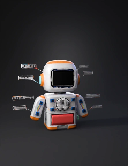
educational robot 3d model
Tags
design
educational robot
machine
machine realistic
machine rendering
machine rendering realistic
realistic
rendering
rendering realistic
Prompt
Objective Design a complete, multi-part, 3D-printable model for a Desktop Companion Robot Chassis that is inspired by the friendly aesthetic of EMO/Vector robots. The robot is static (no wheels) and should look appealing on a desk. The design must accommodate all specified electronic components, ensuring easy assembly and maintenance. I. Overall Design & Aesthetics Style: Friendly, cartoony, and minimalist. Focus on a head/body structure that is proportional to a desk accessory. Access: The body must be split into at least two sections (e.g., Head and Body/Base) or include a removable bottom panel for access to internal wiring and the battery. II. Component Housing and Fit The design must securely hold the following components (Dimensions are crucial): Main Board: A slot/standoffs for the ESP32-C3 LuatOS board. Display (Eye): A square front cutout (bezel) and an internal mounting slot for the 0.96" OLED I2C Display. (Dimensions: Approx. 27mm x 27mm). Power: A dedicated internal bay for the Li-Po Battery (1500mAh) and a slot for mounting the TP4056 USB-C Charger Module. The USB-C port should be accessible from the exterior of the robot's body. Audio Output: An internal chamber for the PAM8403 Amplifier. A grille (perforated mesh/holes) on the front/chest of the robot, suitable for the 8-ohm Speaker (Approx. 45mm diameter) to allow sound to pass clearly. III. Critical Interactive Features (Touch Zones) The chassis must be engineered to enable 6 distinct capacitive touch areas: Touch Sensor Mounting: Create six internal cavities sized for the TTP223 touch modules. Touch Surface Thickness: The exterior plastic wall directly over each TTP223 module must be thin (0.8mm to 1mm maximum) to ensure the capacitive touch signal registers through the material. Touch Zone Placement: Clearly label and position the cavities corresponding to the six interactive zones: Head Top (for petting) Upper Back Left Shoulder/Arm Right Shoulder/Arm Chin/Front Base Front IV. Assembly & Wiring Considerations Component Retention: Include small clips or screw holes (if necessary) to prevent the main boards (ESP32, TP4056) from moving. Wire Routing: Design internal channels or sufficient space to route the necessary wiring (especially the 6 wires from the TTP223 modules) without being pinched.
Detailed Info
Related Models
Enter invite code
Enter invite code to get credits!
 Anonymous1764660416


 Anonymous1764660416