3D Workspace
Home
Assets
Affiliate Program
Sign up/Log in
?
Upgrade
DCC Bridge
Anonymous1768786146
03-25 22:55
Model Name
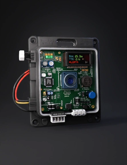
electronics enclosure 3d model
Tags
props
rendering
realistic
Prompt
Photorealistic 3D product render, isometric view at 35° elevation, studio lighting with soft shadows. OBJECT: Electronic enclosure box, ABS plastic, matte dark gray (RAL 7021 Black Gray), dimensions exactly 120mm wide × 80mm tall × 65mm deep. IP65 sealed. Rounded corners radius 8mm all edges. PCB INSIDE (visible through open lid or cutaway top view): Green FR4 PCB, 118×78mm, dual-layer, white silkscreen text visible. COMPONENTS on PCB, precisely positioned: 1. TOP-LEFT ZONE — HLK-LD2410 radar module: rectangular sub-PCB 35mm wide × 15mm tall × 3mm thick, mounted flat, dark green PCB, 3 small rectangular patch antennas (6mm×8mm each) spaced 14mm apart in a row along the top edge, gold-colored copper traces visible. White silkscreen: "HLK-LD2410". Positioned at x=10mm, y=8mm from top-left PCB corner. 2. TOP-CENTER — TF-Luna LiDAR sensor: compact square module 35mm × 35mm × 21mm tall, dark blue housing, prominent circular optical lens 14mm diameter centered on front face, lens has concentric glass rings in deep blue and black, small connector on bottom. White label: "TF-Luna". Positioned at x=42mm, y=6mm. 3. TOP-RIGHT — HC-SR04 ultrasonic sensor: blue PCB 45mm × 20mm, two cylindrical silver transducers 16mm diameter × 12mm tall side by side, separated 18mm center-to-center, metallic mesh grille on each transducer face. White text: "HC-SR04". Positioned at x=72mm, y=8mm. 4. CENTER-LEFT — PIC16F18877 microcontroller: DIP40 IC package, black ceramic body 52mm × 13mm × 4mm, 20 silver pins per side spaced 2.54mm, small white dot orientation marker top-left corner, laser-etched text "PIC16F18877" and "MICROCHIP". Mounted in white DIP40 socket with visible gold-plated contacts. Positioned at x=8mm, y=42mm. 5. CENTER — MAX485 DIP8 IC: black body 10mm × 7mm, 4 pins per side, white "MAX485" text. Positioned at x=66mm, y=46mm. 6. BOTTOM-LEFT — LM2596 DC-DC buck converter module: small green sub-PCB 43mm × 21mm, featuring one blue toroidal inductor 10mm diameter, one blue trimpot (variable resistor), two electrolytic capacitors (8mm tall, black cylinders), silver heatsink pad under main IC. White text: "LM2596 DC-DC". Positioned at x=8mm, y=58mm. 7. BOTTOM-RIGHT — Protection cluster: one P6KE15A TVS diode (small black SMD axial 5mm), one MOV varistor (blue disc 7mm diameter), two electrolytic capacitors 470µF/50V (10mm tall, black aluminum cylinders with white stripe). Positioned at x=74mm, y=56mm. 8. RIGHT EDGE — JST-XH 4-pin connector: white plastic housing 10mm × 8mm, 4 rectangular contacts in a row, cable exit visible. Label: "RS-485 OUT". Positioned at x=108mm, y=50mm. 9. LEFT WALL — Two PG7 cable glands: zinc-alloy silver color, hexagonal body 12mm across flats, 10mm protrusion through wall, rubber sealing washer visible, one with 4-wire shielded cable exiting (black cable, 6mm diameter), one with single cable. Vertical spacing 20mm apart, positioned at y=35mm and y=55mm from top of box. 10. PCB TOP-RIGHT CORNER — Two 5mm LEDs: one green (status OK), one amber (warning), both protruding 3mm above PCB surface, domed lens, visible light emission glow around green LED. BOX EXTERIOR DETAILS: - 4 countersunk M3 stainless steel screws on front face, one at each corner, 8mm from edges - Embossed text on front face: "MJM\CG26" (16pt bold) and "FRONT SENSOR UNIT" (10pt) and "IP65" badge (small oval) - Silicone bead visible around lid perimeter (white/translucent) - 4 nylon M3 standoffs (10mm tall, white) visible inside corners supporting the PCB 10mm above box floor SCENE: White studio background, three-point lighting — key light upper-left, fill light right, rim light behind. Subtle reflection on glossy lid. 4K resolution, product photography style, hyper-detailed, engineering render quality.elevation, warm interior lighting suggesting dashboard environment. OBJECT: Electronic enclosure box, ABS plastic, matte dark charcoal (RAL 7016 Anthracite Gray), dimensions exactly 160mm wide × 120mm tall × 60mm deep. Indoor use (no IP rating required). Rounded corners radius 10mm. Designed to mount on vehicle dashboard. PCB INSIDE (cutaway or open top revealing internals): Green FR4 PCB, 155×115mm, dual-layer, white silkscreen labels. COMPONENTS on PCB, precisely positioned: 1. TOP-LEFT — STM32F030C8T6 on Blue Pill breakout board: small blue PCB 53mm × 23mm, main IC is LQFP48 10mm × 10mm × 1.4mm black package, fine-pitch 0.5mm pins all 4 sides, white silkscreen "STM32F030C8T6" on chip surface. One USB Micro-B connector on left edge of sub-board. Two rows of 20 header pins (2.54mm pitch) along long edges. Sub-board mounted on 8mm tall female headers (floating above main PCB). Positioned at x=8mm, y=8mm. 2. TOP-RIGHT — OLED display module SSD1306 0.96 inch: black PCB 28mm × 27mm, active OLED screen 21mm × 11mm showing glowing cyan text "Dist: 25.3m" on first line, bright green "TTC: 2.1s" on second line, amber "R+ L+ S+" on third line, flashing red "ALERTA" on fourth line. Screen has characteristic OLED deep black background with vivid pixel emission. 4-pin header connector I2C. Positioned at x=95mm, y=8mm. 3. RIGHT SIDE VERTICAL STRIP — LED proximity bar, 5 LEDs in column: All 5mm diameter dome-top LEDs, individually resistored (220Ω SMD 0805 next to each LED): - LED 1 (top): GREEN — emitting visible glow, status "safe" - LED 2: GREEN — dimmer emission - LED 3: YELLOW-AMBER — glowing, "attention" state - LED 4: ORANGE — bright emission "alert" - LED 5 (bottom): RED — intense emission with bright halo, "critical" state. Additional smaller AMBER LED below labeled "FAIL" for sensor failure indication. LEDs spaced 18mm center-to-center in vertical column. Positioned at x=138mm, y=12mm. 4. CENTER-BOTTOM — Piezo buzzer PKM22EPP: round black plastic disc 12mm diameter × 9mm tall, top surface has concentric circular ridges/vents forming acoustic grill pattern, two solder pins on bottom, slight metallic sheen on plastic housing. White silkscreen circle around footprint. Positioned at x=78mm, y=70mm. 5. BOTTOM-LEFT — MAX485 DIP8: black IC 10mm × 7mm × 3mm, 4 silver pins per side, "MAX485" etched in white. Positioned at x=8mm, y=68mm. 6. BOTTOM-LEFT+1 — PC817 optocoupler DIP4: smaller black IC 7mm × 5mm, 4 silver pins, "PC817" label. Adjacent 1kΩ resistor (green/brown band axial, 3mm body). Positioned at x=28mm, y=68mm. 7. CENTER-LEFT — LDR GL5528 photoresistor: round disc 5mm diameter, clear epoxy body with visible zigzag CdS cell pattern visible through lens, two bent wire leads, adjacent 10kΩ resistor. Positioned at x=18mm, y=56mm. 8. BOTTOM — LM2596 DC-DC module: green sub-PCB 43mm × 21mm, same appearance as front box module (toroidal inductor, trimpot, electrolytic caps). Positioned at x=8mm, y=86mm. 9. BOTTOM EDGE — Three connectors in a row: - JST-XH 4-pin (white, 10mm): "RS-485 FROM FRONT" label - 3-pin screw terminal (blue, 12mm): "12V / IGN / GND" label - Single-pin connector: "BUZZER EXT" optional label EXTERIOR DETAILS: - Front face has cutout window 24mm × 14mm for OLED display, thin acrylic cover glued inside - Right side has 5 small round holes (4mm diameter) aligned with LED bar, allowing LED light to be visible from outside when box is closed - Bottom edge has two strain-relief cable exits: one for RS-485 shielded cable (black, 6mm dia), one for power+ignition wires (red+black+yellow, bundled 5mm) - 4 self-adhesive rubber feet on bottom face, 8mm diameter - Embossed text front face: "MJM\CG26" (16pt bold), "DRIVER ALERT UNIT" (9pt), serial number field - Mounting bracket on back: two screw slots for panel screws, plus adhesive patch (3M VHB foam tape, 2mm thick, gray) visible SCENE: Dark automotive dashboard ambient background (blurred), product in sharp focus, three-point studio lighting with amber key light suggesting vehicle interior. LEDs visibly glowing. 4K resolution, product + lifestyle hybrid render.
Detailed Info
Related Models
Enter invite code
Enter invite code to get credits!