3D Workspace
Home
Assets
Affiliate Program
Sign up/Log in
?
Upgrade
DCC Bridge
Anonymous1762273645
11-04 17:29
Model Name
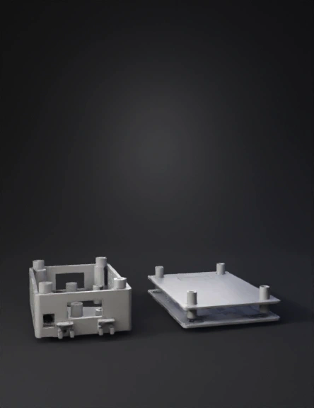
electronic enclosure 3d model
Tags
3d printing
3d printing realistic
electronic enclosure
machine
machine 3d printing
machine 3d printing realistic
machine realistic
realistic
Prompt
## PRECISE 3D MODEL SPECIFICATIONS - TWO PARTS ONLY **COORDINATE SYSTEM:** X-axis = length (left-right), Y-axis = width (front-back), Z-axis = height (vertical up) **OUTPUT REQUIREMENT:** Generate EXACTLY 2 separate STL files - Base part and Lid part. NO additional components. NO separate DIN rail pieces. --- ### PART 1: BASE (Bottom Housing) **OVERALL BASE GEOMETRY:** - Rectangular hollow box oriented horizontally (flat on ground) - External dimensions: X=132.5mm, Y=126.25mm, Z=40mm - Wall thickness: 2mm on all four vertical sides - Bottom floor thickness: 2mm - Top opening: COMPLETELY OPEN (no top surface) - Internal cavity dimensions: X=128.5mm, Y=122.25mm, Z=38mm (40mm minus 2mm floor) **WALL SPECIFICATIONS:** - Front wall (Y-min side): 132.5mm wide × 40mm tall × 2mm thick - Back wall (Y-max side): 132.5mm wide × 40mm tall × 2mm thick - Left wall (X-min side): 126.25mm deep × 40mm tall × 2mm thick - Right wall (X-max side): 126.25mm deep × 40mm tall × 2mm thick - All walls perpendicular to base floor (90° angles) - External corners: 2mm radius fillets **INTERNAL FEATURES - 3 STANDOFF POSTS:** Post 1 (Top-Left): - Center position: X=10mm from left wall inner surface, Y=10mm from front wall inner surface - Cylindrical post: 6mm diameter, 4mm height from floor - Vertical hole through post: 3.2mm diameter, full depth - Post base fully fused to floor Post 2 (Bottom-Left): - Center position: X=10mm from left wall inner surface, Y=112.25mm from front wall inner surface - Cylindrical post: 6mm diameter, 4mm height from floor - Vertical hole through post: 3.2mm diameter, full depth - Post base fully fused to floor Post 3 (Bottom-Right): - Center position: X=118.5mm from left wall inner surface, Y=112.25mm from front wall inner surface - Cylindrical post: 6mm diameter, 4mm height from floor - Vertical hole through post: 3.2mm diameter, full depth - Post base fully fused to floor **CUTOUT 1 - FRONT WALL (Top Edge Terminal Blocks):** - Rectangular opening cut completely through front wall (Y-min side) - Width: 110mm, Height: 13mm - Horizontal center position: X=66.25mm (centered on wall) - Vertical position: Bottom edge of cutout is 25mm from base floor - Edges: 90° square corners, no radius **CUTOUT 2 - BACK WALL (Bottom Edge Terminal Blocks):** - Rectangular opening cut completely through back wall (Y-max side) - Width: 110mm, Height: 13.9mm - Horizontal center position: X=66.25mm (centered on wall) - Vertical position: Bottom edge of cutout is 25mm from base floor - Edges: 90° square corners, no radius **CUTOUT 3 - LEFT WALL (RJ45 Ethernet Port):** - Rectangular opening cut completely through left wall (X-min side) - Width: 16mm, Height: 17.2mm - Vertical center position: 38.104mm from front edge of left wall (Y-min) - Horizontal position: Centered in wall thickness (2mm) - Edges: 90° square corners, no radius **VENTILATION SLOTS - LEFT WALL:** - Pattern of vertical rectangular slots cut through left wall - Each slot: 1mm wide × 15mm tall × 2mm deep (full wall thickness) - Slot spacing: 5mm center-to-center - Vertical position: Slots centered at Z=20mm (middle of wall height) - Horizontal distribution: Evenly spaced along wall, SKIP area occupied by RJ45 cutout - Total slots: approximately 15 slots (avoid RJ45 zone) **VENTILATION SLOTS - RIGHT WALL:** - Mirror pattern of left wall - Each slot: 1mm wide × 15mm tall × 2mm deep - Slot spacing: 5mm center-to-center - Vertical position: Slots centered at Z=20mm - Horizontal distribution: Evenly spaced along entire right wall - Total slots: approximately 18 slots **DIN RAIL CLIPS - INTEGRATED INTO BACK WALL (Y-max side):** CRITICAL: These clips are NOT separate parts. They are solid geometric features molded directly into/onto the back wall exterior surface. Clip 1 Position: Center at X=46.25mm along back wall Clip 2 Position: Center at X=86.25mm along back wall (80mm spacing between clip centers) Each DIN rail clip geometry: - Base attachment: Fused directly to back wall exterior surface - Clip width (X direction): 20mm - Clip projection from wall (Y direction): 10mm - Clip height (Z direction): 30mm - Top hook feature: * Horizontal overhang: 3mm inward * Hook thickness: 3mm * Engages top lip of 35mm DIN rail - Bottom ledge feature: * Horizontal shelf: 5mm wide * Ledge height from base: 7.5mm * Supports bottom of 35mm DIN rail - Clip thickness (material): 3mm throughout - Shape: C-shaped profile when viewed from side **LID ATTACHMENT SCREW BOSSES - INSIDE TOP CORNERS:** Boss 1 (Front-Left corner): - Center position: X=14mm from left wall, Y=14mm from front wall - Cylindrical post extending upward from floor: Diameter 6mm, Height 32mm (reaches near top opening) - Vertical hole: 2.8mm diameter, depth 10mm from top of boss - Boss fully fused to floor and adjacent walls Boss 2 (Front-Right corner): - Center position: X=118.5mm from left wall, Y=14mm from front wall - Cylindrical post: Diameter 6mm, Height 32mm - Vertical hole: 2.8mm diameter, depth 10mm from top - Boss fully fused to floor and adjacent walls Boss 3 (Back-Left corner): - Center position: X=14mm from left wall, Y=112.25mm from front wall - Cylindrical post: Diameter 6mm, Height 32mm - Vertical hole: 2.8mm diameter, depth 10mm from top - Boss fully fused to floor and adjacent walls Boss 4 (Back-Right corner): - Center position: X=118.5mm from left wall, Y=112.25mm from front wall - Cylindrical post: Diameter 6mm, Height 32mm - Vertical hole: 2.8mm diameter, depth 10mm from top - Boss fully fused to floor and adjacent walls --- ### PART 2: LID (Top Cover) **MAIN LID PLATE:** - Flat rectangular plate - External dimensions: X=132.5mm, Y=126.25mm, Z=2mm thickness - Top surface: Completely flat - Bottom surface: Contains internal features **INTERNAL LIP (extends downward from lid bottom surface):** - Rectangular frame around perimeter - Lip external dimensions: X=128.2mm, Y=122mm (0.3mm clearance from base internal cavity) - Lip depth (downward projection): 3mm - Lip wall thickness: 2mm - Lip fits inside base top opening when assembled **LID SCREW BOSSES - 4 CYLINDRICAL POSTS (extend downward from lid bottom):** Boss 1 Position: X=14mm from left edge, Y=14mm from front edge - Cylindrical post extending downward: Diameter 6mm, Length 8mm - Vertical hole: 2.8mm diameter, depth 8mm (full depth) - Aligns with base screw boss 1 Boss 2 Position: X=118.5mm from left edge, Y=14mm from front edge - Cylindrical post: Diameter 6mm, Length 8mm - Vertical hole: 2.8mm diameter, depth 8mm - Aligns with base screw boss 2 Boss 3 Position: X=14mm from left edge, Y=112.25mm from front edge - Cylindrical post: Diameter 6mm, Length 8mm - Vertical hole: 2.8mm diameter, depth 8mm - Aligns with base screw boss 3 Boss 4 Position: X=118.5mm from left edge, Y=112.25mm from front edge - Cylindrical post: Diameter 6mm, Length 8mm - Vertical hole: 2.8mm diameter, depth 8mm - Aligns with base screw boss 4 **OPTIONAL LABEL RECESS (top surface):** - Rectangular depression in top surface - Dimensions: 40mm × 15mm × 0.5mm deep - Position: Centered at X=66.25mm, Y=20mm from front edge --- ### MATERIAL & FINISH SPECIFICATIONS: **Surface Treatment:** - All external surfaces: Matte texture (simulate 0.1mm bead-blast grain) - All edges: 0.3mm chamfer (45°) - Large external corners: 2mm radius fillet - Internal corners: 0.5mm radius fillet **Color:** Light gray (RGB: 180, 180, 180) or RAL 7035 equivalent --- ### ASSEMBLY VERIFICATION: When assembled: - Lid lip inserts into base top opening with 0.3mm gap - 4 lid screw boss holes align with 4 base screw boss holes - M3 screws (10mm length) pass through lid bosses into base bosses - Total assembled height: 40mm (base) + 2mm (lid thickness) - 3mm (lip insertion) = 39mm external - PCB sits on 3 standoff posts at 4mm height inside base - All cutouts allow connector access from outside --- ### OUTPUT FILE REQUIREMENTS: **File 1: Base.stl** - Contains: Base housing with floor, 4 walls, 3 standoffs, all cutouts, ventilation slots, integrated DIN clips, 4 corner screw bosses - Orientation: Base floor on XY plane (Z=0), open top facing +Z direction - Units: Millimeters - Mesh: Watertight, manifold, no errors **File 2: Lid.stl** - Contains: Lid plate, internal lip, 4 screw boss posts - Orientation: Lid top surface on XY plane (Z=0), features facing -Z direction (upside down for printing) - Units: Millimeters - Mesh: Watertight, manifold, no errors **NO OTHER FILES OR COMPONENTS ALLOWED**
Detailed Info
Related Models
Enter invite code
Enter invite code to get credits!