3D Workspace
Home
Assets
Affiliate Program
Creator Program
Sign up/Log in
View Plans
DCC Bridge
alimdiab
01-01 01:02
Model Name
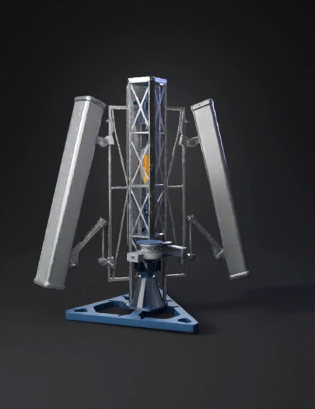
antenna tower 3d model
Tags
antenna
antenna tower
antennas
props
props realistic
props rendering
props rendering realistic
realistic
rendering
rendering realistic
Input
Prompt
Reference image note (important): The uploaded image may show only one antenna. Use it as a template and duplicate it. Final design must include three identical antennas. Design task: Create a mechanically realistic aluminum mounting structure for a pan-tilt head (Aibsin PT-5100) carrying three identical high-gain directional planar antennas, balanced around the centerline. Planar antenna (exact size): 600 × 420 × 135 mm (radome body) Haiyi Jammer Model the antenna as a thick rectangular radome (not a thin panel). The mounting bracket + heatsink/base behind the antenna can add depth; represent this as an additional rear support volume so the total rear protrusion looks realistic (~420–450 mm overall depth including mount, not a thin plate). Base plate: Equilateral triangle, 600 mm per side, 18 mm thick, aluminum 6061-T6 45° beveled edges Central M12 threaded hole at geometric center (PT-5100 mount) Add a stiffened “bumped/sloped” center reinforcement (low pyramidal ribbing) to increase rigidity and reduce wind catch. Tower (must force edge mounting): Use a triangular truss tower (preferred) OR a square truss with 3 defined outer corner posts used Must have clearly defined vertical corner posts Cross-bracing between posts NO bracket attachments on internal bracing or mid-face rails (corner posts only). Mounting height (updated): Antenna centerline height: 450 mm above the base plate (not 1.2 m). All three antennas must be mounted at the same height. Antenna mounts (balanced + directional): Three identical arms, one attached to each tower corner post / edge (120° apart) to distribute weight evenly on the PT head Each arm must attach only to a corner post using clamp plates and gussets Each antenna uses an angled yaw bracket so that although antennas are on different tower edges, all three faces point to the same forward boresight direction. Clearance + spacing: Maintain ≥200 mm free clearance between antennas (edge-to-edge clearance), no overlap. Structural realism: Thick brackets, gusset plates, visible bolts Industrial, wind-resistant look (no thin decorative arms, no floating parts) Style: CAD-like hard-surface model, clean industrial proportions Avoid (must not happen): Brackets mounted in the middle of a tower face Brackets attached to internal braces Antennas pointing outward radially (they must all point forward) Thin flat antennas (must be thick 135 mm radome)
Detailed Info
Related Models
Enter invite code
Enter invite code to get credits!