3D Workspace
Home
Assets
Affiliate Program
Creator Program
Sign up/Log in
View Plans
DCC Bridge
khaled.mohammedcz
10-15 06:25
Model Name
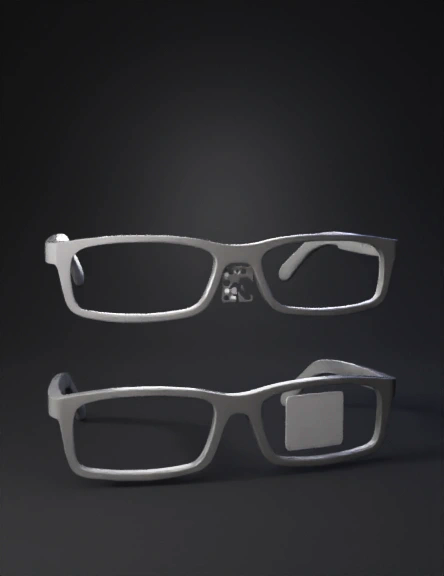
smart glasses 3d model
Tags
glass roofed
housing clear lens
machine
machine realistic
machine rendering
machine rendering realistic
occhiali
realistic
rendering
rendering realistic
smart glasses
spyglass
Prompt
Design a realistic 3D-rendered concept of smart glasses intended for housing embedded electronic components. Overall Design: Style: Modern, matte black finish, minimalist and ergonomic. Shape: Balanced rectangular lenses with slightly rounded corners. Lenses: 52 mm wide × 26 mm high each. Bridge width: 18 mm. Total frame width: 145 mm. Both temples identical externally, each 145 mm long × 22 mm high × 19 mm thick. Wall thickness: 2 mm internal cavity, hollow for components. Both temples have removable top lids (0.2 mm clearance) for assembly and maintenance. Material and Finish: Smooth matte black polycarbonate shell. Minimal seams, no visible screws or markings. Subtle curvature for a comfortable fit behind the ears. Bridge (center between lenses): Contains a rectangular micro speaker (15 × 11 × 3 mm) inside the bridge. On the front of the bridge: a 3×3 grid of round speaker holes, each hole Ø1.2 mm. Speaker grill holes only on the front side, not the back. Left Temple (Power and Charging): Contains the following internal components: Li-Po battery: 3.7 V, 500 mAh, 35 × 20 × 5 mm, front half of temple. USB-C charger board (TP4056-C): 25 × 19 × 2 mm, placed near the rear of temple. USB-C port cutout: 9.2 × 3.6 mm rectangle, located on the top surface near hinge area. Fuel gauge (MAX17048 breakout): 12 × 12 × 2 mm, beside charger board. Load switch (TPS22910A breakout): 10 × 8 × 2 mm, between charger OUT+ and system VIN. Power slide switch: 8.5 × 3 × 3 mm, on the outer side near the hinge (small recess). MEMS microphone (INMP441): 12 × 9 × 3.5 mm, at the front tip, port facing outward. Include a small round mic hole Ø1.5 mm at the front tip of the temple. Right Temple (Main Electronics and Display): Contains the following internal components: ESP32 Dev Board (ESP32-WROOM-32, USB-C): 51 × 26 × 9 mm (mounted diagonally to fit cross-section). Audio amplifier (MAX98357A): 15 × 10 × 3 mm, near ESP32 module. Transparent OLED driver board (Waveshare 1.51″): 60 × 22 × 6 mm, mid-section of temple. OLED screen itself (38 × 30 × 2 mm active area 30 × 15 mm) — attached inside the right lens frame, angled 10–15° inward toward eye. Ribbon cable passes from the driver board to screen through a 1.5 mm wide internal channel. MEMS microphone (INMP441) at the front tip, facing outward, with a mic hole Ø1.5 mm. Two tactile buttons (6 × 6 × 4.5 mm) aligned along the lower outer edge, used for user input (Select / Regenerate Reply). Internal Wiring Channels: Hidden circular tunnels (~2 mm diameter) run through both temples and across the bridge for routing wires and I²C/SPI lines. Wiring from battery (left) to ESP32 (right) crosses under the bridge through a 2 mm internal passage. Design Rules: Both temples must appear identical externally for symmetry. Include a small TPU lid (removable) along the top surface of each temple, flush-mounted. 0.2 mm assembly clearance around lids and removable parts. No overhangs greater than 60°, suitable for 3D printing. No visible markings or logos. Scene / Rendering Setup: Use neutral lighting on a light gray background. Render three views: Left-side view — shows USB-C top port and mic hole. Right-side view — shows mic hole and two buttons. Front view — shows the bridge speaker grille. Optional exploded view: show parts (ESP32, battery, amp, OLED, etc.) hovering slightly above open cavities. Objective: The final render should look like a production-ready prototype for an AI-powered smart glasses system. All dimensions must be realistic and consistent with standard 3D modeling precision. Proportions must match exactly for real-world printability.
Detailed Info
Related Models
Enter invite code
Enter invite code to get credits!