3D Workspace
Home
Assets
Affiliate Program
Creator Program
Sign up/Log in
View Plans
DCC Bridge
jose.chowattukunnel.thomas
10-17 14:17
Model Name
smartguard key fob 3d model
Tags
biometric
fingerprint
key
machine
machine realistic
machine rendering
machine rendering realistic
realistic
rendering
rendering realistic
Prompt
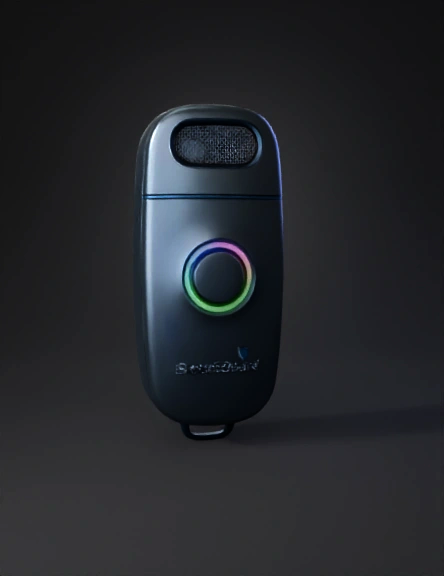
martGuard Key Fob: Technical Feasibility and Deployment Architecture for Safer Driving I. Strategic Context and Market Imperative 1.1 Global Impact of Impaired Driving on Commercial Fleets Drunk driving poses one of the most significant liabilities for commercial enterprises globally, resulting in catastrophic accidents, massive insurance costs, and severe operational disruptions. Organizations, particularly those managing large vehicle fleets in logistics, public transportation, and high-risk sectors (such as fuel or hazardous materials transport), have an acute need for proactive safety solutions. Traditional approaches, primarily using bulky, fixed Ignition Interlock Devices (IIDs) hardwired into the vehicle dashboard, often meet resistance due to installation complexity, high cost per vehicle (CAPEX), and driver discomfort, as the devices are often associated with judicial punishment rather than preventative safety. The SmartGuard Key Fob is designed to address this gap by offering a discreet, portable, high-accuracy alcohol detection system. By integrating the test function into a standard, daily-use device—the key fob—it achieves driver acceptability while maintaining the critical safety function of vehicle immobilization. 1.2 Market Analysis of Ignition Interlock Devices (IIDs) and Fleet Management Systems The commercial adoption of alcohol detection technology is experiencing rapid growth, driven primarily by stringent regulatory measures and an increasing corporate focus on road safety protocols. The global Alcohol Interlocks for Fleets market reached a significant valuation in 2024.1 This market is projected to expand robustly at a Compound Annual Growth Rate (CAGR), reaching a substantial value by 2033.1 North America is a key region for this growth, supported by established regulatory frameworks and strong advocacy from safety organizations.1 The North American market itself is projected to grow at a steady CAGR through 2033.1 Critically, the commercial sector already holds a dominant position within the overall ignition interlock device ecosystem, accounting for a majority of the market share in 2024.2 This substantial existing market share validates the foundational assumption that fleet management and commercial operations represent the most viable and immediate target for the SmartGuard system. Furthermore, the fuel cell technology market share accounts for the majority of the total North America IID market 2, demonstrating a clear market preference for the accuracy and stability provided by electrochemical sensing over lower-cost alternatives. 1.3 Comparative Analysis: Fixed IID vs. Portable Smart Key Fob Traditional IIDs, permanently installed and often requiring invasive hardwiring, suffer from high installation costs and mandate a dedicated device for every vehicle in a fleet. The SmartGuard Key Fob overcomes these issues by providing portability and discreet functionality. The system architecture involves a single portable key fob (the client) used by the driver, communicating with a low-cost, discreet Vehicle Control Module (VCM) (the server) installed in the vehicle. This portability is highly advantageous for large fleets where drivers may switch vehicles frequently, as it allows the fleet manager to track sobriety by the driver, rather than by the vehicle. The system inherently integrates safety directly into the daily routine of key usage, making the process seamless. However, the portable nature creates a singular, major vulnerability: identity verification (cheating). This structural challenge must be counteracted by integrating robust biometric verification mechanisms directly into the key fob design.3 II. Advanced Theoretical Principles of Alcohol Detection To meet the mandatory low BAC thresholds for commercial drivers, the SmartGuard system requires sensing technology based on electrochemical principles, demanding a detailed understanding of the underlying chemical kinetics. 2.1 Fundamental Chemical Principles of Breath Alcohol Sensing Alcohol detection devices measure Breath Alcohol Concentration (BrAC) which is then converted to an inferred Blood Alcohol Concentration (BAC). This conversion relies on Henry’s Law and a standard partition ratio, typically (alcohol in blood versus alcohol in breath). The accuracy of this inference is critically dependent on obtaining a sample of deep-lung (alveolar) air, where the alcohol vapor is in true equilibrium with the blood passing through the pulmonary capillaries. This requirement dictates that the key fob’s inlet design and internal measurement system must enforce specific airflow and volume criteria during the blow test to ensure an adequate sample volume (e.g., mL).4 Failure to collect a deep-lung sample results in a chemically inaccurate reading, requiring the system to invalidate the test. 2.2 Detailed Working Mechanism of the Miniaturized Fuel Cell Sensor The SmartGuard utilizes an Electrochemical Alcohol Sensor, commonly known as a fuel cell, as its sensing element.5 This technology offers superior specificity and stability compared to semiconductor devices.6 The Electrochemical Reaction The sensing element consists of porous Platinum (Pt) electrodes and an acidic electrolyte interlayer.8 The detection process is a redox reaction that adheres to Faraday’s Law. When a breath sample containing ethanol () is introduced: Anode Reaction (Oxidation): Ethanol is oxidized on the working electrode (Anode) surface, releasing hydrogen ions and electrons: (Ethanol is converted to Acetic Acid). Cathode Reaction (Reduction): Oxygen from the ambient air is reduced on the counter electrode (Cathode) surface, consuming the hydrogen ions and electrons generated at the anode: (Oxygen is converted to water). The net reaction releases electrons, creating a current proportional to the mass of ethanol oxidized.5 The system essentially "counts the electrons released by the ethanol molecules" 9 in a fixed volume of air. This generated current produces a quantifiable voltage signal that is directly proportional to the alcohol concentration.8 Miniaturized Fuel Cell Sensor Principle (Conceptual) This diagram illustrates the core mechanism of the electrochemical sensor. It shows the breath sample flow into the sensing chamber, the Platinum electrodes (Anode and Cathode) separated by the acidic electrolyte, and the resulting electrochemical reaction where ethanol is oxidized to create a flow of electrons. The diagram highlights the proportional relationship between the amount of ethanol oxidized and the measurable electrical current generated. Performance and Stability Requirements Miniaturizing this complex chemical process into a key fob requires meticulous engineering. The fuel cell sensor must be highly sensitive and stable.7 Fuel cells also offer fast response times, critical for quick operational use in a fleet environment. While some modules demonstrate response times generally less than seconds 10, high-performance breathalyzer sensors can deliver results in under seconds.11 A significant engineering necessity arising from the fuel cell design is the requirement for temperature regulation and compensation. The kinetics of the electrochemical reaction are temperature-dependent, meaning environmental fluctuations can degrade measurement accuracy. To counteract this, the miniaturized sensor module (such as the ZE31-C2H5OH) must incorporate an integrated temperature sensor. The Microcontroller Unit (MCU) must then apply computational compensation algorithms to the raw sensor signal to maintain stable readings across the operating temperature range (e.g., to ).7 2.3 Critical Performance Metrics: Accuracy, Specificity, and Calibration Fuel cell sensors are inherently superior to semiconductor sensors in terms of specificity, meaning they selectively react with alcohol molecules, providing excellent anti-interference characteristics against common gases like carbon monoxide (CO).7 This specificity is non-negotiable for commercial applications. However, all portable breathalyzers are susceptible to measurement "drift," which necessitates routine calibration to ensure good accuracy.6 Maintaining the strict regulatory accuracy required for commercial limits (less than BAC) requires frequent calibration checks. The system must aim for minimal measurement error, typically F.S. (Full Scale).10 The operational implication of this requirement is that the SmartGuard device must be designed for centralized maintenance. While some sensors are pre-calibrated at the factory 12, operational deployment requires ongoing drift management. The MCU must incorporate internal diagnostics and health monitoring algorithms. If the sensor’s baseline output (zero reading) or span drifts beyond pre-set acceptable parameters, the key fob must self-lock and report a "Service Required" message to the central fleet management system, preventing its use until re-calibration is performed. This proactive measure ensures regulatory compliance and prevents erroneous operational downtime caused by device inaccuracy. III. SmartGuard System Architecture and Operational Flow The SmartGuard architecture employs a two-component design: the portable Key Fob (Client) and the Vehicle Control Module (VCM) (Server). This separation ensures that the sensing and identity verification are portable, while the high-security functions of vehicle immobilization remain hardwired and protected within the vehicle. 3.1 Architectural Overview: Key Fob (Client) and Vehicle Control Unit (Server) Communication Model The Key Fob is the intelligent client, handling sensing, processing, biometric identity verification, and secure wireless transmission. The VCM is a discreet unit hardwired into the vehicle's ignition system. It acts solely as a secure receiver, validator, and physical controller. Communication between the two devices is established through a short-burst, ultra-low-power Bluetooth Low Energy (BLE) link. 3.2 The Three-Step Verification Protocol (Sense, Process, Act) Step 1: Sense (The Secured Biometric Blow Test) The process begins when the driver presses the test button. Concurrently, the driver must place their finger on the integrated fingerprint scanner. This step mandates dual-verification: identity authentication via biometrics and breath sample collection. The fuel cell sensor then analyzes the sample, generating an electrical signal proportional to the BrAC.5 Flow control mechanisms to ensure a deep-lung sample volume (e.g., mL) is captured.4 If the sample is insufficient, the test is immediately invalidated, forcing a re-test. Step 2: Process (The Secure Decision) The MCU receives the analog voltage signal from the fuel cell sensor. It applies the necessary temperature compensation algorithms, using the onboard temperature sensor data.7 The corrected BrAC reading is then converted to an inferred BAC percentage and compared against the predefined fleet safe limit (e.g., ). Simultaneously, the MCU verifies the driver's fingerprint against stored, encrypted biometric templates.13 A highly secure digital decision is generated: PASS (Low alcohol level, verified identity), FAIL (High alcohol level), or TAMPER (Biometric mismatch or insufficient sample). Step 3: Act (Immobilization Handshake) If the decision is PASS, the MCU initiates a secure BLE transmission burst. A cryptographic payload containing the verified authorization ID, the PASS code, and a secure timestamp is sent to the VCM. The Key Fob lights a green RGB LED. If the decision is FAIL or TAMPER, the MCU logs a violation internally. The key fob illuminates a red LED and remains deliberately silent; no BLE signal authorizing ignition enablement is transmitted to the VCM. The vehicle ignition remains disabled. 3.3 Fob Subsystem Breakdown and Decision Logic The core logic must manage several failure states: A Biometric Mismatch indicates a circumvention attempt, leading to a system lock-out for a penalty period and a logged violation. An Alcohol FAIL similarly results in a lockout and violation log. The MCU serves as the security gatekeeper, ensuring that both identity and sobriety criteria are met before the critical BLE transmission is permitted. 3.4 Vehicle Interface Subsystem (VCM) and Immobilization Interface The VCM is hardwired into the vehicle. Upon receiving a BLE transmission, the VCM validates the encrypted payload's integrity, timestamp, and authorization ID. Only if the handshake is secure and verified, the VCM activates an internal control relay to enable the vehicle’s ignition. The physical interruption mechanism relies on an external relay interrupt installed directly onto a low-current, critical vehicle circuit. This is typically the starter solenoid activation wire or the main ignition power line.14 This method is the most reliable, non-intrusive approach for aftermarket fleet deployment.16 Factory vehicle immobilizers use proprietary transponder codes transmitted via an antenna to the SMARTRA interface, which communicates with the Engine Control Unit (ECU) to release the engine electronics.17 However, attempting to integrate the SmartGuard system directly into the highly complex, encrypted, and proprietary Controller Area Network (CAN) bus protocols used by modern ECUs presents significant risk. Direct intervention could void vehicle warranties, create diagnostic fault codes, and compromise vehicle systems.18 Therefore, the SmartGuard architecture mandates using a secure, external, relay-based kill switch controlled by the VCM. This isolates the critical safety feature from the core vehicle network, ensuring reliability and maintainability. SmartGuard System Architecture Diagram (Conceptual) This diagram details the secure interaction between the portable Key Fob (Client) and the Vehicle Control Module (VCM) (Server). It shows the flow of data starting from the biometric scan and breath test, processing the PASS/FAIL decision in the MCU, and culminating in the secure Bluetooth Low Energy (BLE) payload transmission to the VCM. The VCM's connection to the physical Starter Enablement Relay is depicted as the final link in the system's control chain. IV. Component Engineering, Miniaturization, and Power Management Miniaturizing a high-accuracy detection system into a key fob form factor presents significant engineering hurdles, particularly regarding power efficiency and component integration. The device must achieve a multi-year battery life using a small coin cell while handling the power demands of sensor heating, biometric scanning, and wireless communication. 4.1 Core Processing Unit Selection for Ultra-Low Power (ULP) The MCU must perform complex tasks: signal conditioning, floating-point arithmetic for temperature compensation and BAC calculation, biometric template matching, and running the low-power BLE stack. The selection favors integrated System-on-Chips (SoCs) with high processing capability coupled with ultra-low power consumption. The use of the 32-bit ARM Cortex-M4F core (found in solutions like the Nordic nRF52832 or nRF52840) is essential.20 The "F" denotes a Floating-Point Unit (FPU), which significantly accelerates the calculation of BAC using complex sensor algorithms and temperature compensation models. This speed is vital for minimizing the time the chip spends in the high-power active state. Older Cortex-M0 or 8-bit cores lack the necessary speed and efficiency for this level of signal processing.21 Advanced SoCs, such as the Renesas DA14592, offer world-class, ultra-low hibernation current consumption, measured at only 22, which is crucial for achieving long shelf life. 4.2 Miniaturized Sensor Integration The physical dimensions of the components constrain the key fob size. High-accuracy fuel cell sensors, such as the Mini Cell Sensor, are relatively small, with dimensions around mm.4 The mechanical design must incorporate the sensor, the MCU, the battery, the fingerprint reader, and the antenna within a durable, ergonomically sound housing. Crucially, the external mechanical design must ensure proper airflow management to capture the required mL sample volume while protecting the sensitive sensor element from dust and moisture. SmartGuard Key Fob Industrial Design (Conceptual) This illustration depicts the miniaturized, ergonomic external form factor of the SmartGuard Key Fob. Key features shown include the mouthpiece/air inlet (optimized for deep-lung air sampling), the integrated, low-profile capacitive fingerprint sensor on the side panel for concurrent authentication, the test activation button, and the tri-color (RGB) status LED indicating PASS/FAIL/TAMPER states. 4.3 Wireless Communication: Bluetooth Low Energy (BLE) Protocol Stack BLE is selected for its extremely low power consumption profile, making it suitable for coin cell operation.23 While high-speed Bluetooth (Basic/Enhanced Data Rate) can consume up to and peak currents up to , BLE significantly reduces power consumption (depending on the use case), with peak current consumption typically below .23 In its idle or deep sleep state, the BLE device draws current in the microamp () range, often around to .24 The strategy for power optimization centers on aggressive duty cycling: the device remains in deep sleep for of the time and only enters the high-current active state for brief periods (e.g., 5 seconds) during the test and transmission cycle. The power system faces a challenge during the brief, high-current peaks required for BLE transmission (TX/RX) and active sensor sampling, where current draw can reach to .23 A CR2032 coin cell battery cannot maintain voltage stability under such peak loads, leading to momentary voltage droops (e.g., from down to ).25 If unmanaged, this droop can trigger a system reset or failure. The power design must therefore incorporate high-value, low-Equivalent Series Resistance (ESR) capacitors (e.g., Multi-Layer Ceramic Capacitors, MLCCs) immediately before the MCU and BLE module. These capacitors act as energy reservoirs, buffering the voltage during the high-current burst, ensuring system stability.25 4.4 Power System Design and Longevity Calculation The SmartGuard is powered by a standard CR2032 Lithium Coin Cell battery, offering approximately mAh capacity.26 Maximizing battery life depends entirely on minimizing the current drawn during the Deep Sleep state and strictly controlling the duration of the active phases. Power Management Duty Cycle Model (Conceptual) This graph visually contrasts the continuous, low-level Deep Sleep current (μA range) against the brief, sharp spikes representing the Active State (Sensor activation, Biometric scan, BLE TX/RX) in the mA range. The area under the Deep Sleep curve would overwhelmingly dominate the total energy budget, demonstrating the effectiveness of the ULP component selection. V. Anti-Cheating Mechanisms and Regulatory Compliance The portability of the SmartGuard Key Fob introduces the inherent risk of circumvention, where a sober individual performs the breath test ("friend blow") to enable the vehicle for the impaired driver. To ensure integrity and meet regulatory requirements, hardware-based identity verification is mandatory. 5.1 Integration of Biometric Authentication The solution utilizes integrated biometric authentication to ensure that the individual providing the breath sample is the authorized, registered driver.3 This capability is supported by existing legal precedent and patents governing interlock systems, which outline the ability of a system to lock a mechanical device if a real-time biometric scan does not match a stored image of an authorized operator.13 The system must employ a small-profile, low-power capacitive fingerprint sensor (such as the ZW20/ZW3020 type).29 Capacitive sensors offer a fast recognition speed suitable for the brief active cycle of the key fob. The operational workflow requires the driver to maintain finger placement on the scanner during the breath test procedure. The system's central logic dictates that if the biometric scan fails to match the authorized user's template, the key fob immediately enters a TAMPER state, prevents the breath test result from being processed, and inhibits the transmission of the ignition-enable signal.13 The sensor must utilize "push finger detection" to minimize power consumption in standby, activating the high-current scanning process only when contact is made.30 5.2 Rolling Re-Testing and Compliance Logging To prevent a driver from consuming alcohol immediately after a successful start, or allowing a sober passenger to initiate the vehicle, the system must enforce mandatory rolling re-tests, a standard procedure for all IIDs. Since the SmartGuard is a portable key fob, the VCM must be programmed to periodically prompt the driver (via vehicle visual/auditory cues) to perform a re-test. This requires the VCM to confirm the presence of the authorized key fob within the cabin via strong BLE signal monitoring. The driver must perform the re-test, including the concurrent biometric scan, within a short, non-negotiable window (e.g., 60 seconds). Failure to comply with the rolling re-test initiates a logged violation and a non-critical engine shutdown or alarm sequence (depending on regulatory requirements, immediate engine shutdown may be dangerous, so a safe limp mode or alarm is often preferred). The system must maintain a non-erasable, time-stamped log of all key events, including: successful tests, failed tests, biometric failures (circumvention attempts), power consumption anomalies, and dates of calibration. 5.3 Secure Vehicle Immobilization Interface The VCM’s role is to securely translate the wireless authorization into physical vehicle control. The secure relay control mechanism must be isolated and robust against tampering. The VCM controls an automotive-grade relay which interrupts the electrical circuit necessary for engine start. The most effective method is interrupting the signal wire running to the starter solenoid.14 Aftermarket Starter Kill Relay Wiring Schematic (Conceptual) This diagram shows the secure, external relay interrupt mechanism. It illustrates a standard 12V automotive relay connected to the vehicle's starter solenoid activation wire, ensuring engine immobilization. The VCM is shown controlling the relay coil (Terminals 85/86), which, when energized by the authorized PASS signal, closes the critical power path (Terminals 30/87) to the starter solenoid, enabling engine cranking. 14 VI. Prototyping and Simulation Methodology To validate the integrated sensing, processing, and communication architecture before committing to costly custom hardware manufacturing, a two-phase prototyping strategy using accessible platforms is recommended. 6.1 Phase 1: Rapid Hardware Prototyping The initial phase utilizes off-the-shelf development boards, such as the Nordic nRF52 Development Kit or an ESP32 board, which feature integrated BLE and sufficient processing power. This phase allows engineers to validate the complex analog-to-digital signal chain of the commercial fuel cell sensor module (like the ZE31-C2H5OH), perform real-world testing of the BAC calculation algorithms, and most importantly, measure actual current draw during active and deep sleep states to definitively validate the power model outlined in Table 4. 6.2 Phase 2: Virtual Simulation Environment Detail The second phase uses virtual tools—Tinkercad and MIT App Inventor—to model the system logic and the critical communication layer, which is invaluable for development and instructional purposes. 6.2.1 Tinkercad Circuit Modeling: Using Potentiometer as a Calibrated Alcohol Proxy In the Tinkercad environment, a virtual Arduino circuit is built. The expensive fuel cell sensor is simulated using a simple Potentiometer.34 The rotary dial of the potentiometer acts as an analog proxy for the BrAC level: turning the dial represents increasing alcohol concentration, outputting an Analog-to-Digital Conversion (ADC) reading between and . The Arduino code logic dictates that the MCU reads this analog input. A threshold value (e.g., ) is set to simulate the legal BAC limit. If the reading is below (sober, PASS), the Arduino sends a specific serial character (e.g., 'G' for Go) via a simulated Bluetooth/Serial link. If the reading exceeds (drunk, FAIL), it sends a different character (e.g., 'R' for Stop). An RGB LED in the simulation visually confirms the decision.35 Figure 5: Simulated Fob Circuit (Conceptual) This figure depicts the basic simulation circuit layout in Tinkercad, demonstrating the Fob's core logic. It includes the Potentiometer (acting as the alcohol sensor proxy) connected to an Analog pin of the Arduino (MCU), and a color-changing LED connected to a Digital Output pin (representing the vehicle status). The diagram illustrates how the Arduino's code reads the analog input and generates a corresponding visual output. 34 6.2.2 MIT App Inventor Application Development for Dashboard Display and Data Handshake A smartphone application is created using MIT App Inventor to simulate the VCM and the in-vehicle dashboard display. This app manages the wireless connection and user interface output.39 The app uses the BluetoothLE component to scan, connect, and receive data from the Tinkercad simulation.39 The app is programmed to constantly monitor the incoming serial character stream ('G' or 'R'). This process demonstrates the critical data handshake protocol: Upon receiving the authorized 'G' character, the app updates the display to show: "CAR UNLOCKED: IGNITION ENABLED." Upon receiving the 'R' character, or if no data is received within the timeout period, the app displays: "WARNING: ALCOHOL DETECTED! IGNITION DISABLED." The simulation's profound value lies in modeling this communication layer.42 It reinforces the principle that the vehicle system (simulated by the App) is passive and remains immobilized until it receives the specific, authenticated, and compliant signal from the external security device (the simulated Fob). This proves the concept of secure, digital authorization translating into physical control. VII. Implementation Challenges, Commercialization, and Future Roadmap 7.1 Legal and Data Privacy Considerations The integration of biometric authentication introduces complex legal requirements, particularly concerning data privacy. Biometric data, such as fingerprints, constitutes Sensitive Personal Information (SPI) under regulations like the EU's General Data Protection Regulation (GDPR) and the California Consumer Privacy Act (CCPA). The system must be designed to minimize risk by securely hashing the biometric data and storing templates locally on the key fob or within the VCM's secure element. Centralized transmission of raw biometric data must be avoided. Fleet operators must establish clear, verifiable consent policies for driver enrollment, data retention limits, and secure access protocols. The legal compliance framework is paramount for market acceptability, particularly in highly regulated international jurisdictions. 7.2 Manufacturing and Bill of Materials (eBOM) Optimization The primary drivers of manufacturing cost (eBOM) are the high-accuracy fuel cell sensor and the integrated ARM Cortex-M4F SoC/BLE module. Commercial viability relies on optimizing the eBOM for mass production. This involves selecting highly integrated components. For instance, SoCs like the Renesas DA14592 are marketed for requiring typically only six external components 22, minimizing board complexity and reducing assembly cost. By using highly integrated solutions, the need for external components, such as a sleep mode crystal, can be removed, further supporting cost reduction and miniaturization.22 7.3 Commercialization Strategy The commercialization strategy must focus on high-liability sectors such as oil and gas, hazmat transport, and public transit, where the cost of a single accident vastly outweighs the cost of the safety system. The implementation model should utilize a mandatory subscription service structure. This subscription covers the centralized, mandatory calibration and maintenance necessary to maintain the sensor's regulatory accuracy, secure data management (log files, violation reporting), and over-the-air firmware updates for the VCM and key fob. 7.4 Future Technology Roadmap Future development phases should focus on enhancing integration and security: Fleet Telematics Integration: The VCM should be developed to communicate test results, violation logs, and associated timestamps to the central fleet management dashboard. This communication can be integrated into existing telematics systems, utilizing protocols like J1939 or J1979 for data extraction only, minimizing risk to the control systems.43 Passive Sensing: Research should be dedicated to next-generation sensor technologies, such as transdermal alcohol monitoring, which could be integrated into the fob casing or steering wheel. This could allow for continuous, seamless monitoring of the driver’s alcohol rate without requiring an explicit blow test, shifting the system toward completely non-intrusive safety management.9 Enhanced Authentication: Integrating GPS location services into the VCM allows for verification of the vehicle's location during failed tests or circumvention attempts. Furthermore, implementing rolling biometric checks during operation (fingerprint or facial recognition via an integrated dash camera connected to the VCM) combined with the rolling breath re-test ensures the highest level of ongoing driver authentication. VIII. Conclusion The SmartGuard Key Fob represents a practical and technologically advanced solution to the persistent problem of impaired driving in commercial fleets. By leveraging miniaturized, high-accuracy fuel cell sensing, ultra-low-power ARM Cortex-M4F processing, and secure Bluetooth Low Energy communication, the design proves that multi-year operation on a coin cell battery is feasible. The inherent portability of the fob streamlines fleet operations, reducing the logistical burden and cost associated with fixed IIDs. Crucially, the architecture mitigates the primary risk of portability—cheating—by mandating concurrent biometric authentication and utilizing a highly secure, relay-based ignition interrupt mechanism independent of proprietary vehicle control systems. The system is fundamentally driven by the need for precision, stability, and verifiable identity. Implementation requires meticulous attention to power duty cycling, mechanical durability, and strict adherence to emerging data privacy regulations governing biometric data. The SmartGuard Key Fob provides a robust platform for enhancing road safety and reducing catastrophic risk across the commercial transport sector. make more original
Detailed Info
Related Models
Enter invite code
Enter invite code to get credits!