3D Workspace
Home
Assets
Affiliate Program
Creator Program
Sign up/Log in
View Plans
DCC Bridge
k0919565
09-27 17:48
Model Name
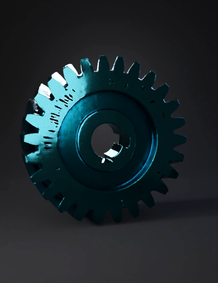
spur gear 3d model
Tags
central bore
machine
machine realistic
machine rendering
machine rendering realistic
realistic
rendering
rendering realistic
spur gear
Prompt
// Tars Al-Halazuni Al-Muzdawaj (Herringbone Gear) // Based on the provided engineering drawing. // NOTE: Standard gear parameters (Module, Pressure Angle) are estimated // as they are not explicitly defined in the drawing in a standard format. // ========================================================= // 1. Defining Standard Gear Parameters (Estimated for Functionality) // ========================================================= // Module (m): Determines the size of the teeth. (2mm is common for 3D printing) m = 2; // Number of Teeth (N): Estimated visually from the top view. N = 20; // Pressure Angle (p): Standard angle for involute gears. p = 20; // Helical Angle (alpha_h): The angle of the 'V' slope (estimated visually at 30 degrees) alpha_h = 30; // ========================================================= // 2. Dimensions from the Drawing // ========================================================= // Bore Diameter (D_bore): 0.9 (units, assuming mm) D_bore = 0.9; // Keyway Depth (d_keyway): 0.19 (from the center line to the flat) d_keyway = 0.19; // Face Width (L_total): The overall axial length of the teeth (using 2.4 as the face width of each segment and adding a small gap) L_segment = 2.4; L_gap = 0.2; L_total = (L_segment * 2) + L_gap; // ========================================================= // 3. Calculated Parameters // ========================================================= // Pitch Diameter (Dp = m * N) Dp = m * N; // Outside Diameter (Do = Dp + 2*m) Do = Dp + 2*m; // Twist Angle (Calculated based on helical angle and face width) // This is the total twist applied over the segment length. twist_angle = (L_segment / Dp) * 360 * tan(alpha_h); // ========================================================= // 4. Main Module to Create the Gear // ========================================================= module herringbone_gear() { // 1. Create the first helical half (Half A) // Twist applied is positive translate([0, 0, L_total / 2 - L_segment / 2]) linear_extrude( height = L_segment, twist = twist_angle, slices = 100 ) { // Placeholder for Gear Profile - must be replaced with a proper involute profile. // For a correct gear, ensure you are using a proper involute_gear() module. // Example: involute_gear(m=m, N=N, p=p); // --- Using a simple polygon approximation for the spur gear profile to show the twist effect --- $fn = N * 5; // Higher detail circle(d=Do); // ------------------------------------------------------------------------------------------------ } // 2. Create the second helical half (Half B) // Twist applied is negative (or mirrored) translate([0, 0, L_total / 2 + L_segment / 2]) mirror([0, 0, 1]) { translate([0, 0, L_total / 2 - L_segment / 2]) // Re-aligning the translation for the mirror linear_extrude( height = L_segment, twist = twist_angle, // Same angle, but mirrored on the Z-axis slices = 100 ) { // Placeholder for Gear Profile - must be the same as above $fn = N * 5; circle(d=Do); } } // 3. Central Bore Cutout difference() { // The combined helical gear shape translate([0, 0, -L_total/2]) // Center the gear model around Z=0 children(); // This holds the two halves created above // Cylinder for the Bore cylinder(d=D_bore, h=L_total * 2, center=true); // Keyway Cutout // Flat width at depth d_keyway keyway_width = 2 * sqrt((D_bore/2)^2 - (D_bore/2 - d_keyway)^2); // Making the keyway cut deeper than the gear length translate([0, -(keyway_width / 2), 0]) cube([D_bore * 2, keyway_width, L_total * 2], center = true); } } // ========================================================= // 5. Final Rendering
Detailed Info
Related Models
Enter invite code
Enter invite code to get credits!