3D Workspace
Home
Assets
Affiliate Program
Sign up/Log in
?
Upgrade
DCC Bridge
3D Creation Made Simple
Text & Image to 3D Model in seconds
One-Click Texturing & Smart Detail Editing
Free Credits Monthly
Start Free
Anonymous1764309872
11-28 07:33
Model Name
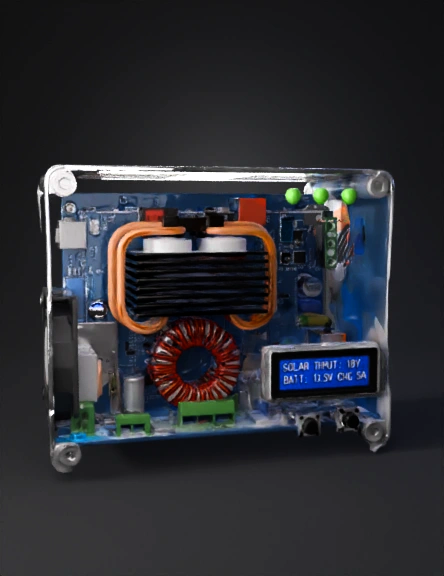
transparent electronics enclosure 3d model
Tags
machine
rendering
realistic
Prompt
The following is a Standard Operating Procedure (SOP) for creating a 3D model of a CC-CV (Constant Current-Constant Voltage) Solar Battery Charger, focusing on the controller's Printed Circuit Board (PCB) and its Enclosure.📏 Phase 1: Planning and MeasurementThis phase establishes the foundational data required for accurate 3D modeling.1. Define Design SpecificationsA. Determine Component Selection: Identify the key electronic components for the CC-CV controller (e.g., MOSFETs, Inductors, Capacitors, Microcontroller/IC, terminal blocks).B. Define PCB Outline: Specify the exact length, width, and thickness of the main Printed Circuit Board (PCB).C. Define Interface Layout: Determine the position and size of external components that will pass through the enclosure, such as:Input/Output Terminal Blocks (Solar Input, Battery Output, Load Output).Heatsinks (if used, for power components like MOSFETs).Displays/LEDs (if present).Cooling Fan size and position (if needed).2. Gather Dimensions and DatasheetsA. Component CAD Models: Source or measure the exact dimensions and 3D models (often in .step or .iges format) for the key components (IC, largest inductor, capacitors, terminal blocks, heatsink).B. Enclosure Size: Determine the final external dimensions of the controller's housing (Length x Width x Height) and the wall thickness.💻 Phase 2: 3D Modeling the Components and PCBThis phase focuses on building the electronic and physical models of the core device.3. Create/Import Component ModelsA. Import Standard Components: Import the 3D CAD models for common components (terminal blocks, fuses, fan, etc.) using their .step or .iges files.B. Model Custom Components: For proprietary or generic parts (like the main IC, custom heatsink, etc.), create simplified but dimensionally accurate 3D models.Crucial Focus: Ensure the models correctly represent the height, footprint, and any interference points.4. Model the PCB AssemblyA. Model the PCB Base: Create a rectangular block (or custom shape) representing the PCB outline using the dimensions from Phase 1.B. Place Components: Position and align the 3D component models onto the PCB base according to the circuit board's layout.Goal: Create a complete 3D PCB Assembly model. This is critical for ensuring the enclosure has proper clearances.📦 Phase 3: 3D Modeling the EnclosureThis phase designs the physical casing that will house and protect the electronics.5. Design the Main Enclosure BodyA. Define Envelope: Create the overall outer shell of the enclosure (often a box shape) based on the target dimensions.B. Shell the Body: Apply a shell operation to create the desired wall thickness (e.g., $2\text{ mm}$ or $3\text{ mm}$).C. Add Mounting Features: Design internal bosses or standoffs for securing the PCB assembly inside the enclosure (e.g., using M3 screws).6. Create Interface Openings and FeaturesA. Terminal Openings: Cut holes for the input/output terminal blocks and power cables.B. Cooling Features: Add ventilation slots or cutouts for the cooling fan and heatsinks.C. Display/Button Cutouts: Create windows or openings for any LEDs, display screens, or user buttons.D. Fastening Features: Design interlocking features, screw holes, or latches for assembling the enclosure parts (e.g., the main body and a removable cover).✅ Phase 4: Review and Final ExportThis is the final check and preparation of the model for use.7. Perform Interference CheckA. Assembly Check: Place the completed 3D PCB Assembly model inside the 3D Enclosure model.B. Clearance Verification: Use the 3D modeling software's interference detection tool to ensure:No component (especially tall parts like capacitors or the heatsink) is colliding with the enclosure walls or lid.There is adequate airflow clearance around heatsinks and vents.Component ports align perfectly with the external openings.8. Finalize and ExportA. Generate Files: Save the final enclosure design as a stereolithography file (.stl) for 3D printing.B. Documentation: Create technical drawings with key dimensions and material specifications for manufacturing or sharing.Would you like to focus on the design considerations for thermal management (heatsinks/fans) within the 3D model?
Detailed Info
Related Models
Enter invite code
Enter invite code to get credits!