3D Workspace
Home
Assets
Affiliate Program
Sign up/Log in
?
Upgrade
DCC Bridge
Anonymous1770287292
02-05 10:43
Model Name
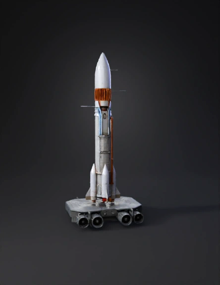
heavy lift rocket 3d model
Tags
boosters
realistic
rendering
rendering realistic
vehicle
vehicle realistic
vehicle rendering
vehicle rendering realistic
Prompt
The image shows a heavy‑lift launch vehReference and Planning Image Reference: Use the uploaded image as a background in Blender. You can set it as a reference image in the 3D Viewport: Shift + A → Image → Reference → select your file. Align it to the correct view (front or side) for precise modeling. Analyze Components: Nose cone / command module Main rocket body / stages Boosters Fuel tanks Engines Support structures 2. Base Shapes Blender works best by starting with simple geometric shapes: Command Module / Nose Cone: Add a cone (Shift + A → Mesh → Cone). Use subdivision surface modifier to smooth it. Main Body: Use a cylinder (Shift + A → Mesh → Cylinder). Adjust the number of vertices (32–64) for smoothness. Use loop cuts (Ctrl + R) to add detail for panels or segments. Boosters: Duplicate cylinders and scale them for the correct size. Add caps (top/bottom) using Ctrl + E → Cap or Mesh → Faces → Fill. 3. Detailing the Rocket Engines: Model a basic nozzle using a cone and cylinder. Add loop cuts for pipes and inner details. Consider array modifier to duplicate small components like exhaust tubes. Fuel Tanks and Pipes: Use cylinders and torus meshes for curved pipes. For complex pipe networks, use Bezier curves → convert to mesh (Curve → Convert → Mesh from Curve). Panels and Lines: Use edge loops and the knife tool (K) to cut lines. Extrude (E) or inset (I) for panel details. 4. Modifiers for Efficiency Subdivision Surface: Smooth curved surfaces. Mirror Modifier: Model one side of symmetrical parts (like boosters or engine clusters). Array Modifier: Repeat components (like small pipes, bolts, or engine details). Boolean Modifier: Cut or merge complex shapes (useful for internal parts or docking ports). 5. Materials and Textures Assign different materials for metal, fuel tanks, and engine nozzles. Use Principled BSDF shader for realistic metal reflections. Optional: Use UV unwrapping for decals or NASA logos. Consider emission shader for engine flames or exhaust glow. 6. Lighting and Rendering Use an HDRI environment for realistic lighting. Place a key light to simulate the sun and fill lights for details. For flames or engine fire: Use a volume shader or particle system. Render with Cycles for photorealism or Eevee for faster previews. 7. Optional: Animation Animate rocket launch: Animate position along Z-axis. Add smoke/fumes using Blender’s smoke simulation. Engine glow via animated emission shader. Tips for Realism Keep the scale consistent – rockets are very tall, so use real-world scale. Add small details like bolts, panels, and hoses for realism. Use reference images from multiple angles if available. Work in stages: block out → detail → materials → render. If you want, I can create a step-by-step Blender workflow diagram specifically for this rocket, showing how to build it layer by layer with modifiers, materials, and engines. This would make it much easier to visualize the modeling process.icle displayed in a cutaway (cross‑section) view, meaning part of the outer structure is removed to reveal the internal systems. The design is similar to modern NASA‑style rockets used for deep‑space missions. The rocket is standing vertically on a launch pad and consists of three main sections: Upper section (crew or payload) Central core stage (fuel and main structure) Lower propulsion section (engines and thrust systems) It also includes two large side boosters for additional power during liftoff. 1. Upper Section – Payload / Crew Module At the very top of the rocket is the payload or crew capsule, protected by a smooth, cone‑shaped outer shell. Purpose: Carries astronauts or cargo (such as satellites or spacecraft) Designed to withstand extreme heat and pressure during launch and re‑entry Key features: Aerodynamic shape to reduce air resistance Structural frame beneath the outer shell Connection to the upper‑stage engine below 2. Upper‑Stage Engine (Inside the Cutaway) Just below the capsule, inside the rocket, is a gold‑colored upper‑stage engine. Purpose: Used after the rocket reaches space Provides precise thrust to place the payload into orbit or send it toward the Moon or deep space Characteristics: Smaller than the main engines Highly efficient Optimized for vacuum conditions 3. Central Core Stage – Fuel System The middle section of the rocket contains large propellant tanks, clearly visible in the cutaway. Fuel Tanks: Hydrogen Tank – stores liquid hydrogen fuel Oxygen Tank – stores liquid oxygen (oxidizer) These tanks are stacked vertically and connected by pipes and valves. Color‑coded piping: Blue pipes: fuel flow Orange pipes: oxidizer or high‑temperature systems Purpose: Feed fuel and oxygen to the engines Maintain pressure and temperature during flight 4. Side Boosters (Solid Rocket Boosters) On both sides of the core stage are two large cylindrical boosters. Purpose: Provide massive thrust during liftoff Help the rocket overcome Earth’s gravity Key facts: They burn for the first few minutes of flight After burnout, they are typically detached and discarded or recovered 5. Lower Section – Main Engines At the bottom of the rocket are multiple powerful main engines. Purpose: Generate the primary thrust during launch Push the entire rocket upward Features: Large engine nozzles Extremely high temperatures and pressure Complex plumbing for fuel delivery Structural mounts to absorb vibration and force Visible flames indicate active thrust during launch. 6. Structural and Support Systems Throughout the rocket you can see: Structural frames Electronic systems Control units Heat shielding Sensors and power connections These systems: Keep the rocket stable Control direction and speed Monitor performance and safety Summary This rocket is a modern heavy‑lift launch system designed for: Human spaceflight Deep‑space exploration Large payload delivery The cutaway view helps illustrate: How fuel flows through the rocket How engines are staged How different systems work together as one integrated machine If you want, I can also: Simplify this explanation for school level Explain it like a presentation script Compare it to real rockets (SLS, Saturn V, etc.) Label each part step‑by‑step
Detailed Info
Related Models
Enter invite code
Enter invite code to get credits!