3D Workspace
Home
Assets
Affiliate Program
Creator Program
Sign up/Log in
View Plans
DCC Bridge
21091a0453
07-26 02:22
Model Name
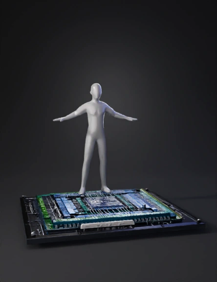
microprocessor die 3d model
Tags
machine
machine realistic
machine rendering
machine rendering realistic
realistic
rendering
rendering realistic
style
visualization
Prompt
The model you generated looks like a **PCB/electronic board**, whereas **ICC2 GUI** displays a **physical layout database** with routing layers, power mesh, standard cells, macros, pins, congestion, etc. For an ICC2-style visualization, don't ask for a "3D power delivery model." Instead, describe the internal ASIC layout. Use a prompt like this: ## ICC2 GUI Style 3D Prompt **Create a highly detailed 3D cutaway visualization of an ASIC Physical Design floorplan in Synopsys ICC2 GUI style.** The chip should be shown as a semi-transparent silicon die with every physical design layer visible. Include: - Core boundary - Die boundary - IO Pads around the die - VDD/VSS Power Pads - Thick Power Ring around the core - Vertical M8 Power Straps - Horizontal M7 Power Straps - Dense Power Mesh - Thousands of Via Arrays connecting every metal layer - Metal Layers M9 down to M1 - Standard Cell rows - Millions of standard cells
Detailed Info
Related Models
Enter invite code
Enter invite code to get credits!
 21091a0453


 21091a0453