3D Workspace
Home
Assets
Affiliate Program
Creator Program
Sign up/Log in
View Plans
DCC Bridge
Anonymous1773159945
03-13 12:44
Model Name
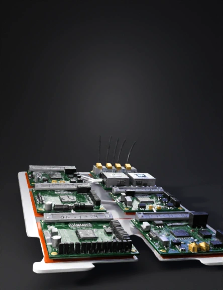
green pcb assembly 3d model
Tags
adapter
electrical
electronics
gpu
machine
machine realistic
machine rendering
machine rendering realistic
realistic
rendering
rendering realistic
Prompt
The neural adapter is built as a multi-stage electronics module that converts neural electrical activity into digital data for processing by the GPU and then converts processed digital signals back into safe neural stimulation patterns. The adapter is divided into five functional blocks: neural signal acquisition, amplification, analog-to-digital conversion, digital translation, and neural output stimulation. Each block must be assembled sequentially and tested independently before integration with the GPU and neural interface system. The first stage is the neural signal acquisition stage. This stage connects electrodes to the scalp or neural interface contacts and routes those signals into a differential amplification circuit. Neural signals are extremely small, usually in the microvolt to millivolt range, so high-impedance instrumentation amplifiers are required. A suitable amplifier for this stage is the Texas Instruments INA122 Instrumentation Amplifier or the Analog Devices AD627 Instrumentation Amplifier. These amplifiers provide high input impedance and low noise performance necessary for detecting weak biological electrical signals. The amplifier is mounted on a small PCB near the electrode connector to minimize noise pickup from long traces. Each electrode pair connects to the differential input pins of the amplifier. A reference electrode is connected to the system ground reference used by the analog front-end. After amplification, the signal passes through analog filtering circuits. A band-pass filter removes irrelevant frequencies. Typical neural signals fall between approximately 0.5 Hz and 500 Hz, so a two-stage RC or active filter is used to attenuate frequencies outside this range. Capacitors and resistors are placed after the amplifier output to build a low-pass and high-pass filtering stage. This filtering stabilizes the signal before it enters the analog-to-digital converter. The next stage is analog-to-digital conversion. The amplified and filtered signal must be digitized so it can be processed by digital systems such as FPGAs and GPUs. A specialized biopotential converter such as the ADS1299 family can be used. This chip integrates multiple programmable gain amplifiers and 24-bit simultaneous sampling ADC channels designed specifically for EEG and other biological measurements. The ADS1299 can capture up to eight channels of neural signals and sample them at rates between 250 samples per second and 16,000 samples per second while maintaining very low input noise. A simpler modular ADC alternative is the ADS1256 24‑bit 8‑channel ADC module. This module can digitize analog signals with high resolution and is widely used in data acquisition systems. The output from the instrumentation amplifier stage connects directly to the analog input pins on this ADC module. Once the neural signal has been digitized, the digital output must be handled by a control processor capable of managing high-speed data transfer and mapping the neural data into computational inputs for the GPU. This is performed by an FPGA development board. A suitable platform is the Digilent Basys 3 FPGA Development Board or the Alchitry Cu V2 FPGA Development Board. The ADC connects to the FPGA using an SPI interface consisting of clock, data-in, data-out, and chip select lines. The FPGA reads digitized neural samples, buffers them, and formats them into structured data packets. The FPGA performs several tasks simultaneously. It synchronizes ADC sampling, filters or compresses neural data if necessary, and packages the signal stream into a format compatible with the GPU interface. If the GPU is connected through a PCIe expansion bridge, the FPGA can implement a PCIe controller core that streams neural data directly into system memory accessible by the GPU. Alternatively, the FPGA can transmit neural data to a host processor that forwards it to the GPU over standard high-speed interfaces. The next block of the adapter is the isolation stage. Electrical isolation is essential to protect neural tissue from high-power electronics used by the GPU system. Optical isolators separate the neural electronics from the rest of the system while still allowing digital communication to pass through. A suitable module is the Optical Isolator Signal Module or similar opto-isolator breakout boards. These devices transmit signals using light internally, preventing direct electrical conduction between the neural electronics and the GPU system. All digital lines leaving the FPGA toward the GPU interface pass through the isolation module. The final stage is the neural stimulation output driver. This stage converts processed GPU signals back into controlled electrical pulses that can interact with neural tissue through electrodes. Because neural stimulation must be extremely precise, a regulated current source is used. One example is a laboratory-grade precision current source such as the Vernier Constant Current System. In a compact adapter design, a miniature current-controlled driver circuit can be built using an operational amplifier and precision resistors to maintain microamp-level current output. The FPGA controls this driver through a digital-to-analog conversion stage, generating pulses that mimic natural neural firing patterns. Assembly of the adapter begins with the analog acquisition PCB. Instrumentation amplifiers and filtering components are soldered first, along with electrode connectors. The analog outputs are then routed to the ADC module through short shielded traces. The ADC module is connected to the FPGA board using SPI wiring and ground references. The FPGA is powered from a regulated 3.3-volt supply and configured with firmware capable of reading ADC data continuously. After verifying that neural signals can be captured and digitized, the optical isolation module is inserted between the FPGA and the rest of the computational system. This ensures that the neural front-end remains electrically isolated from the GPU hardware and power systems. Finally, the neural output driver is connected to the FPGA’s digital-to-analog output pins, allowing controlled stimulation signals to be generated. Testing is performed in stages. First the amplifier stage is tested using a signal generator producing microvolt-level test signals. Next the ADC output is verified by monitoring digital data streams on the FPGA. After digital communication is confirmed, the isolation stage is inserted and verified with test signals. Finally the output driver is tested using resistive loads before connecting any biological interface. The completed neural adapter functions as a bridge between biological neural signals and high-performance computational systems. It captures neural activity through electrodes, amplifies and digitizes the signals, processes them through FPGA logic, isolates them from high-power electronics, and generates safe stimulation outputs controlled by GPU-based computation. show what this should look like when completed
Detailed Info
Related Models
Enter invite code
Enter invite code to get credits!