3D Workspace
Home
Assets
Affiliate Program
Creator Program
Sign up/Log in
View Plans
DCC Bridge
jainivashjan1
01-26 16:00
Model Name
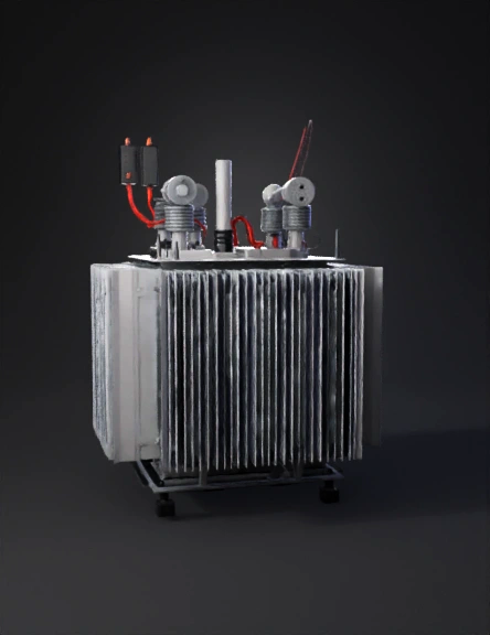
transformer health monitor 3d model
Tags
electronics
machine
machine realistic
machine simulation
machine simulation realistic
monitor
realistic
simulation
simulation realistic
transformers
Prompt
The proposed system is a real-time transformer health and remaining-life estimation solution designed for distribution-level transformers. The system focuses on monitoring critical parameters that directly influence transformer aging, such as oil temperature, load current, and ambient temperature. Sensor data is collected using non-invasive hardware mounted externally on the transformer. An embedded edge controller processes this data locally to estimate transformer health based on thermal stress and load conditions. The system computes a health score that represents the current condition of the transformer and provides an estimate of its remaining operational life. Unlike conventional systems that rely on fault detection, the proposed system enables preventive maintenance by identifying early signs of degradation. The system is designed to be low-cost, scalable, and suitable for field deployment without requiring modifications to existing transformer infrastructure. Data can be transmitted to a monitoring dashboard for visualization, alerts, and maintenance planning. 5. SYSTEM ARCHITECTURE The system architecture explains how data flows from the transformer to the monitoring system. It is designed to be simple, reliable, and suitable for field deployment. Overall Working 1. Sensors collect transformer data 2. ESP32 processes the data locally 3. Health condition is calculated 4. Data is sent to monitoring dashboard ________________________________________ Architecture Layers 1. Sensing Layer This layer measures physical parameters from the transformer: • Oil temperature • Load current • Ambient temperature These values indicate how much thermal stress the transformer is undergoing. ________________________________________ 2. Edge Processing Layer • ESP32 collects sensor data • Basic calculations are done locally • Transformer health score is generated This reduces dependence on cloud and enables faster response. ________________________________________ 3. Communication Layer • ESP32 sends processed data using Wi-Fi • Only essential data is transmitted • Reduces network usage ________________________________________ 4. Monitoring Layer • Displays transformer condition • Shows alerts when health degrades • Helps maintenance planning ________________________________________ 6. HARDWARE DESCRIPTION AND IMPLEMENTATION The hardware design focuses on minimum components, low cost, and non-invasive installation. ________________________________________ 6.1 Hardware Components Used 1. Oil Temperature Sensor • Measures transformer oil temperature • Most important factor for transformer aging • Mounted on transformer oil tank surface Why needed: Higher oil temperature → faster insulation aging ________________________________________ 2. Load Current Sensor (CT Sensor) • Measures transformer load current • Detects overload conditions • Installed by clamping around LV output conductor Why needed: Overloading increases internal heating ________________________________________ 3. Ambient Temperature Sensor • Measures surrounding temperature • Helps understand cooling effectiveness Why needed: High ambient temperature reduces heat dissipation ________________________________________ 4. ESP32 Microcontroller • Collects sensor data • Calculates health score • Sends data to monitoring system Why ESP32: Low cost, built-in Wi-Fi, sufficient processing power ________________________________________ 5. Power Supply Unit • Converts available supply to safe DC voltage • Ensures stable operation of electronics ________________________________________ 6.2 Hardware Integration – Step by Step Step 1: Sensor Placement • Oil temperature sensor fixed on oil tank • CT sensor clamped on LV output line • Ambient sensor placed near transformer ________________________________________ Step 2: Wiring and Connections • Sensors connected to ESP32 GPIO pins • Proper insulation and secure wiring used • Power supply connected through fuse ________________________________________ Step 3: ESP32 Programming ESP32 is programmed to: • Read sensor values periodically • Filter incorrect readings • Store data temporarily • Perform basic calculations ________________________________________ Step 4: Health Calculation • Temperature rise and load duration are analyzed • Health score is updated continuously • Abnormal conditions are detected early ________________________________________ Step 5: Data Transmission • ESP32 sends data using Wi-Fi • Includes: o Oil temperature o Load current o Ambient temperature o Health score ________________________________________ Step 6: Protection and Safety • Surge protection devices used • Proper grounding provided • Weatherproof enclosure protects hardware ________________________________________ Step 7: Testing • Sensor values verified manually • Load variation tested • Health score behavior observed ________________________________________ 6.3 Integration with Existing Transformers • No internal modification required • No power shutdown required • Completely external monitoring unit • Safe for live installation this is my and add a another addition of maintain the transformer current lines and there is three lines supply in a transformer if any lines is defect the hardware helps to find the defect lines thorugh the hardware and give alert to system administrator through mobile app
Detailed Info
Related Models
Enter invite code
Enter invite code to get credits!
 jainivashjan1


 jainivashjan1