3D Workspace
Home
Assets
Affiliate Program
Sign up/Log in
?
Upgrade
DCC Bridge
Anonymous1771991485
02-25 04:08
Model Name
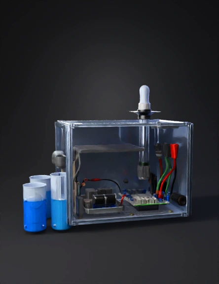
sensor enclosure 3d model
Tags
electronics
machine
machine realistic
machine rendering
machine rendering realistic
realistic
rendering
rendering realistic
sensor enclosure
Prompt
The Sensor Probe Assembly (The "W1. The Housing Model (External Shell) The goal here is visibility and protection. You want the judges to see the "intelligence" inside while proving the device is rugged. The Container: Use a high-transparency IP67 polycarbonate box. This allows you to show off your neat wiring and the ESP32’s onboard LEDs. Sealing: Use black rubber cable glands at the bottom. This is where the sensor wires exit. Using glands shows you understand "waterproofing"—if you just drill holes, it looks unprofessional. The Beacon: Drill a hole at the very top for your frosted RGB LED. Placing it at the highest point ensures it acts like a "lighthouse" that can be seen from 360 degrees. Mounting: Model a "Mounting Wing" using 3D printing (PLA or PETG filament). It should look like a clamp that can slide onto a bucket rim or a 2-inch PVC pipe. 2. The Sensor Probe Assembly (The "Wet" Side) You shouldn't just let the sensors hang loosely in the water. You need to model a Sensor Cluster. The Shield: Design a 3D-printed sensor cage or use a wide PVC pipe with holes drilled into the sides. This protects the delicate glass of the pH probe and the optics of the turbidity sensor from being hit by rocks or debris in the well. Internal Alignment: Align the sensors so they are all at the same depth. The Turbidity sensor should be in the middle so that bubbles (which can mess up readings) don't get trapped in its light path. 3. The Electronic Layout (The "Dry" Side) Inside the box, the model should look like a finished product, not a science experiment. Custom PCB or Perfboard: Instead of a "spaghetti" of loose jumper wires, use a perfboard or a custom-designed PCB. Group your components: Power Corner: Solar charging module and battery. Logic Center: The ESP32. Signal Edge: Resistors and connectors for the sensors. Wire Management: Use heat-shrink tubing or small zip-ties. Label your wires (e.g., "pH," "TDS," "Power") so anyone looking at the prototype understands the circuit immediately. 4. The Power Modeling The Solar Bracket: Model a swivel mount for the solar panel. This shows that you’ve considered how the sun moves throughout the day in the Philippines. Battery Safety: Place the 18650 battery in a dedicated plastic holder bolted to the bottom of the box. This prevents it from rattling and breaking the ESP32 during transport. 5. The "First Flush" Simulation Setup For your demonstration, you need to model the Testing Environment: Two-Tank System: * Tank A (The Baseline): Clean, clear water (Blue LED). Tank B (The Contaminated): Water mixed with a bit of soil and a drop of vinegar (to change pH). The Action: Moving the sensor cluster from Tank A to Tank B should trigger the Flashing Red alert within 2 seconds. This proves the First Flush Algorithm is active and working.et" Side) You shouldn't just let the sensors hang loosely in the water. You need to model a Sensor Cluster. The Shield: Design a 3D-printed sensor cage or use a wide PVC pipe with holes drilled into the sides. This protects the delicate glass of the pH probe and the optics of the turbidity sensor from being hit by rocks or debris in the well. Internal Alignment: Align the sensors so they are all at the same depth. The Turbidity sensor should be in the middle so that bubbles (which can mess up readings) don't get trapped in its light path.
Detailed Info
Related Models
Enter invite code
Enter invite code to get credits!