3D Workspace
Home
Assets
Affiliate Program
Sign up/Log in
?
Upgrade
DCC Bridge
Anonymous1765233353
01-10 14:30
Model Name
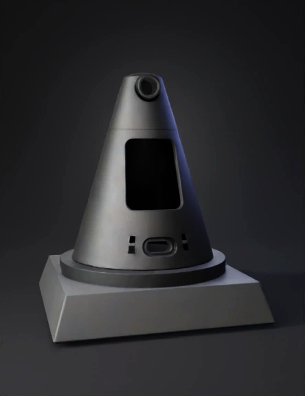
cone sensor enclosure 3d model
Tags
3d printing
3d printing realistic
machine
machine 3d printing
machine 3d printing realistic
machine realistic
realistic
sensor enclosure
Input
Prompt
TRIPO 3 – LOCKED FINAL CAD PROMPT (V5.0) PRODUCTION STL / 3D PRINT READY NO TEXT / NO LOGOS / NO ELECTRONICS / NO LED OBJECTS / NO SUPPORTS REFERENCE Use the attached image as the ONLY exterior design language reference: same cone taper, same silhouette, same base platform proportions, same overall look. This is NOT a render; generate a manufacturable STL. OBJECTIVE Generate ONE single-piece, fully hollow smart cone enclosure: - Fully hollow interior from base to top (continuous empty cavity) - No internal mounts, no internal frames, no solid volumes, no electronics - Printable without supports (all overhangs ≤ 45°) - Clean, sharp industrial geometry like the reference SCALE / PROPORTION UPDATE (IMPORTANT) Because the new screen window is smaller, scale the entire cone + base DOWN by 8–10% relative to the previously approved version (overall scale 0.90–0.93), while keeping the same visual proportions as the reference image. WALL THICKNESS (LOCKED) - Cone body wall thickness: 2.4mm - Base wall thickness: 3.0mm - Around openings: keep walls as thin as possible internally (no double walls), so future sensors can sit close to the front and slightly protrude if needed. FRONT MAIN SCREEN WINDOW (LOCKED – MUST BE PERFECT RECTANGLE) - Opening is a TRUE rectangular cutout only (no trapezoid) - Size: 35.0mm (width) × 58.0mm (height along cone axis) - Rounded corners: R2.5 - ABSOLUTELY NO inner lip, NO ledge, NO step, NO internal bezel, NO rear bracket, NO internal frame, NO recessed pocket - Immediately behind the window: empty cavity (fully hollow) TOF OPENING (ONLY ONE – NO EXTRA HOLES ANYWHERE BELOW) - Located centered below the screen window, aligned to reference placement - Shape: capsule / oval opening (rounded ends) - Size: 10.0mm (width) × 18.0mm (height) - Front wall thickness at ToF area: EXACTLY 0.7mm - Do NOT model the sensor; do NOT show any sensor shape - CRITICAL: REMOVE COMPLETELY any secondary hole or slot under the ToF (no extra hole, no pass-through, no additional opening) LED SLOTS (HOLLOW CUTOUTS ONLY, ALIGNED WITH TOF LINE) - Add minimal LED slots as true hollow cutouts (open through the wall) - Place them on the same horizontal line / alignment as the ToF area - Slot size: 2.0mm width × 2.0mm depth (cut through the wall) - Reduce quantity; keep clean and minimal - No LED housings, no internal channels, no inserts TOP CAMERA OPENING (HOLLOW MOUNT ONLY) - At the top area like the reference: one circular opening / recess - Only a hollow functional cavity (no camera geometry) - Keep printable without supports USB PORT (ONLY ONE, OPEN MORE, ON RIGHT SIDE OF BASE – LIKE THE IMAGE) - Only ONE USB opening total - Size: 12mm × 6mm with rounded corners - Fully hollow through the wall - Placement: on the RIGHT side of the BASE (right side of the image), not on the front face and not near the central window plane. - Make it more open/clear as a real port opening (no thin “almost closed” slot) BASE / PRINTABILITY - Base shape and stance must match reference - Entire model must be printable with 0 supports: all internal bridges/overhangs self-supporting ≤45° - Single watertight manifold STL body, no splits OUTPUT Return ONE final STL-ready model only. NO variations. NO extra details. NO text. NO arrows. NO numbers.
Detailed Info
Related Models
Enter invite code
Enter invite code to get credits!