3D Workspace
Home
Assets
Affiliate Program
Creator Program
Sign up/Log in
?
Upgrade
DCC Bridge
Anonymous1759159970
09-29 15:38
Model Name
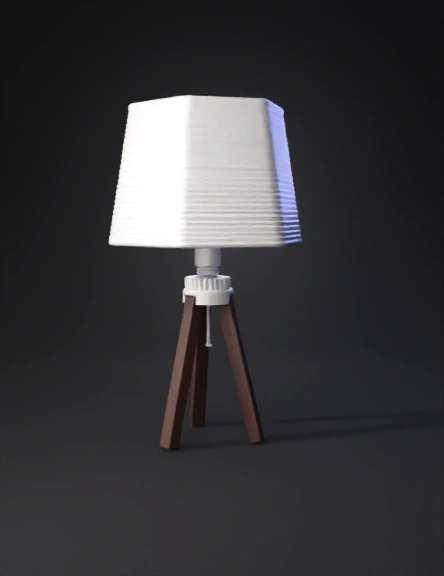
tripod lamp 3d model
Tags
3d printing
3d printing realistic
fabric lampshades
fenerbah
light wood
props
props 3d printing
props 3d printing realistic
props realistic
realistic
sidelights
streetlamp
tripod lamp
Input
Prompt
Project name: Tripod E27 lamp — layered horizontal shade with fuzzy texture Units: millimeters (mm) — export final STL in millimeters, binary, manifold. Overall constraints Overall lamp height: 254 mm (10 in) Base (tripod) height: 150 mm Shade outer dimensions: Length (X) 200 mm × Breadth (Y) 180 mm × Height (Z) 100 mm Shade wall thickness: 3 mm (uniform) Print tolerance / clearance: +0.5 mm on holes where a commercial E27 socket or retaining ring will be inserted (so parts fit after printing). Main parts to output as separate STL files lamp_shade.stl — the hollow shade body (with integrated groove pattern and top connection geometry). lamp_base_tripod.stl — the tripod base with center mounting boss and socket housing interface. retaining_ring.stl (optional) — a printable outer ring / nut that tightens the shade onto the E27 socket boss. Shade geometry & surface details Outer shape: an octagonal/rounded rectangular form with softly chamfered/rounded edges that fits 200 × 180 mm footprint and 100 mm tall. Outer shape should read as smooth in silhouette but composed of stacked horizontal layers. Internal cavity: hollow with uniform 3 mm wall thickness; interior top opening sized for the E27 socket boss (see boss dims below). Add internal ledge(s) where the ring will seat to clamp the shade. Horizontal line pattern: full-wrap horizontal ridges/grooves across the entire outer shade. Implement as concentric stacked layers: groove pitch 3 mm (center-to-center) with groove depth 1.5 mm (i.e., 1.5 mm depression between ridges) so the pattern is visible when 3D printed and gives a “stacked / layered” aesthetic. Ridges should be gently rounded at their tops (0.5 mm radius) to avoid sharp edges. Shade surface texture (fuzzy look): model a micro-bump displacement across outer surface with amplitude 0.25–0.5 mm and random small-scale noise frequency to produce a soft, fuzzy tactile appearance when printed — not sharp spikes, but gentle micro-asperities. (If the chosen generator cannot do displacement, use a fine noise / bump map baked into the geometry or export at high mesh resolution.) Socket & shade connection Create a center mounting boss on the top of the base and a matching counterbore / collar in the shade top so the shade sits concentric. Clearance hole for E27 socket neck: create a through hole diameter 28.5 mm (provides ~+0.5 mm clearance over 27 mm nominal). Retaining method (as requested): model an outer ring seating feature on the shade underside and a matching threaded boss on the base/socket housing sized to accept a standard E27 outer ring. Because E27 ring nut sizes vary, provide a printable retaining ring model included as retaining_ring.stl that screws onto the boss — make the boss OD 40 mm and the ring ID 39.2 mm so the ring is a snug-fit (approx 0.8 mm interference on plastic threads). Also add 0.5 mm clearance between shade seating surfaces so tightening the ring compresses the shade slightly. If you prefer a simple method, also include a flat clamp-seating alternative: a shoulder + M3 screw boss (three radial M3 screw bosses) so a commercial E27 socket can be fixed with screws and the shade secured by the printed ring. (Including both methods is handy.) Base / tripod Tripod with three evenly spaced legs (120° apart), connecting to a central hub. Legs should be sized for stability: leg cross-section rectangular 18 mm × 12 mm (adjust for desired look). Corner rounding: round all external leg corners with 1.0 mm fillet (user requested 1 mm). Chamfer any internal corners slightly to avoid stress concentrators. Leg texture: apply the same fuzzy micro-texture as the shade but lower amplitude ~0.25 mm, blended toward the bottom so prints look cohesive. Central hub must include the socket boss described above and internal cavity to host an E27 socket (clearance + screw bosses if desired). Mechanical & printing design rules Wall thickness: min 3 mm for shade, min 4–5 mm for structural parts of base/hub. Fillets/Chamfers: all load-bearing transitions should have at least 1 mm fillets. Legs corners: 1 mm fillet as requested. Threading: if including printable threads, use coarse trapezoidal or square threads sized for 3D printing (2.5–3 mm pitch). For the retaining ring, model a simple buttress-style coarse thread for reliable print and stronger engagement. Provide also a friction-fit snap groove if user prefers snap assembly. Holes & screw bosses: design M3 boss pockets with 0.2–0.4 mm extra clearance for tapping; provide through-holes for screws with countersinks if needed. Supports & print orientation: shade: print upright (open bottom down) to preserve horizontal texture alignment and minimize support inside. Base/tripod: print standing with legs up or on side depending on slicer to minimize overhangs. Provide drain holes (2–3 mm) for resin/filament printing inside cavities. Export and mesh quality Output each part as separate, watertight (manifold) STL files. Mesh resolution: high — ensure the horizontal pattern and fuzzy micro-displacement are preserved (target ~0.5–0.8 mm mesh edge length or finer where details exist). Check and repair non-manifold edges, flipped normals, and self-intersections before exporting. Materials & printing recommendations (suggestions) Filament: PLA+ or PETG for quick prototyping; ASA for outdoor use; resin printing will give best surface detail for the fuzzy look but requires hollowing and drain holes. Layer height recommendation: 0.12–0.2 mm for visible horizontal ridges. Infill: shade internal: 0–15% with solid top/bottom shells (unless making it load-bearing), base: 20–30% for stability. Post-processing: light sanding the ridge tops for soft highlights; if preserving fuzzy texture, minimal sanding. Extra deliverables to request from the AI/CAD generator Parametric model (Fusion 360 or STEP) with named parameters: overall_height, base_height, shade_L, shade_W, shade_H, wall_thickness, groove_pitch, groove_depth, boss_ID, boss_OD. This lets you easily tweak sizes later. Assembly animation / exploded view showing how shade, socket, ring, and base fit. A printable retaining ring (separate STL) and a short text file listing recommended hardware (E27 socket brand, screws, ring nut outside diameter if you want to buy a commercial piece).
Detailed Info
Related Models
Enter invite code
Enter invite code to get credits!
 Anonymous1759159970


 Anonymous1759159970