3D Workspace
Home
Assets
Affiliate Program
Sign up/Log in
?
Upgrade
DCC Bridge
Anonymous1770793969
02-13 04:42
Model Name
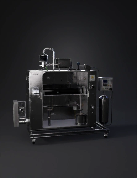
lab microwave reactor 3d model
Tags
machine
rendering
realistic
Prompt
Use this as a single prompt for Tripo3D (you can copy‑paste it directly): Create a high‑detail 3D model of a laboratory‑scale microwave methane pyrolysis reactor system, analogous to a compact industrial research setup described in Korean patents on microwave carbon receptors and methane reforming.KR101995128B1-1.pdf+1 The whole system should be shown as one integrated skid on a metal frame, with all main units clearly visible and connected by pipes and cables. The style should be realistic, clean, slightly technical/industrial, with clearly recognizable components and no interior building environment.[ppl-ai-file-upload.s3.amazonaws] Describe and include these elements explicitly: Microwave reactor chamber A rectangular metal microwave cavity (like a small industrial microwave oven) made from stainless steel, with rounded edges, ventilation slots, and a front access door.KR101995128B1-1.pdf+1 The front door should have a small rectangular viewing window covered by a fine metal mesh (grid size clearly less than 3 mm) to indicate microwave shielding.[ppl-ai-file-upload.s3.amazonaws] On one side of the cavity, show a standard rectangular waveguide port (WR340‑type) connected to the magnetron.[ppl-ai-file-upload.s3.amazonaws] The cavity should be mounted on a rigid frame with four legs and bolted to the skid. Quartz tube reactor inside the cavity Through the center of the microwave cavity, place a horizontal transparent quartz tube reactor.Otchet.pdf+1 Quartz tube outer diameter: visually around 20–30 mm, wall thin enough to look like glass, length extending slightly beyond both sides of the cavity.Otchet.pdf+1 Inside the central hot zone of the quartz tube, show a packed bed of dark carbon particles (activated carbon / coal char) forming the “microwave carbon receptor” bed.KR101995128B1-1.pdf+1 In the middle of the packed bed, place a thin thermocouple (K‑type) inserted from the top or from one side, with a ceramic feedthrough on the reactor wall; label it T1.[ppl-ai-file-upload.s3.amazonaws] Near the tube outlet, place a second thermocouple (T2) to measure gas temperature downstream.[ppl-ai-file-upload.s3.amazonaws] Gas inlet section (bottom / left side) At the inlet side of the quartz tube, add a stainless‑steel gas distributor/spurger: a short vertical piece connected to the tube with a flange or fitting, and at its bottom a cylindrical sparger with multiple tiny holes 0.2–0.5 mm (can be shown as a perforated ring).[ppl-ai-file-upload.s3.amazonaws] Connect two small gas lines to the inlet manifold: one labeled “CH4” (methane) and one labeled “N2 / Ar” (inert gas for purging).Otchet.pdf+1 Each gas line should pass through a compact mass flow controller (small box with digital display and cables) mounted on a nearby panel or frame, then connect by thin stainless tubes to the inlet.KR101995128B1-1.pdf+1 Magnetron and waveguide Above or to the side of the microwave cavity, add a standard 2.45 GHz magnetron: a metallic cylindrical block with cooling fins and a ceramic output, connected to a rectangular waveguide section.[ppl-ai-file-upload.s3.amazonaws] Show the waveguide (WR340‑like rectangular duct) leading directly into the microwave cavity side wall.[ppl-ai-file-upload.s3.amazonaws] Add high‑voltage and control cables from the magnetron to a power supply box mounted on the skid.[ppl-ai-file-upload.s3.amazonaws] Power and control panel Next to the cavity, place an electrical control cabinet with: Main power switch and emergency stop button Digital readouts for T1 and T2 Indicators for microwave power level A small microcontroller/PLC module (e.g., Arduino‑style board) connected via cables to thermocouples, magnetron power (through a solid state relay), and gas flow controllers.[ppl-ai-file-upload.s3.amazonaws] Optionally label the cabinet “Microwave Pyrolysis Control”. Gas outlet and solid carbon collection On the outlet side of the quartz tube, add a short insulated pipe leading to a small cyclone separator or vertical metal filter housing to collect solid carbon (soot / carbon black).Otchet.pdf+1 Below the cyclone/filter, add a removable collection pot for solid carbon.[ppl-ai-file-upload.s3.amazonaws] Downstream of the solid separator, show a line going to a simple gas purification unit: either a water seal (transparent container partially filled with water, with gas bubbling through), or a compact PSA/sorbent cartridge (vertical cylinder) labeled “H2 purification”.[ppl-ai-file-upload.s3.amazonaws] After purification, show a gas outlet line labeled “H2 product”. Safety and shielding details The entire microwave cavity should be fully enclosed by metal walls; clearly show that no microwaves can escape except through shielded openings.[ppl-ai-file-upload.s3.amazonaws] Add small pressure gauges on the gas inlet or outlet lines to indicate pressure monitoring.Otchet.pdf+1 Optionally include a hydrogen gas detector box on the frame near the outlet line.[ppl-ai-file-upload.s3.amazonaws] Add warning labels on the cavity: “Microwave radiation hazard” and “Hot surface”. Overall proportions and environment Scale: laboratory / pilot‑scale system, roughly the size of a large lab instrument (about 1–2 meters long skid).Otchet.pdf+1 The model should be free‑standing, not inside a building, with neutral background. Use realistic metallic materials (brushed stainless steel, aluminum), transparent glass‑like material for quartz, dark matte material for carbon bed, and plastic/colored accents for cables and control units. Emphasize: Clear visibility of the quartz tube, carbon packed bed, and microwave cavity. The analogy to a Korean microwave carbon receptor reactor: quartz tube with carbon bed as microwave receptor inside a multimode microwave cavity, gas lines for CH4 and inert gas, thermocouples T1/T2, magnetron plus waveguide, and downstream solid carbon and hydrogen handling.KR101995128B1-1.pdf+2 Do not add people, flames, or open combustion. The system must look like a closed, safe, engineered laboratory microwave methane pyrolysis reactor.Otchet.pdf+1Also, split the entire 3D model into two clearly separated parts to reveal the internal structure. One half should show the complete external appearance of the system (closed metal microwave cavity, shielding, piping, cabinet), while the other half should be a cutaway view with the front and top of the microwave cavity removed so that the quartz tube, carbon packed bed, thermocouples T1 and T2, gas distributor/sparger, and internal routing of the tube through the cavity are clearly visible. The cutaway side must still include all external components (magnetron, waveguide, gas lines, outlet, cyclone, purification unit), but with the microwave chamber itself visually open so that the internal reactor layout is easy to see.
Detailed Info
Related Models
Enter invite code
Enter invite code to get credits!