3D Workspace
Home
Assets
Affiliate Program
Creator Program
Sign up/Log in
View Plans
DCC Bridge
jpenglis2000
01-15 13:48
Model Name
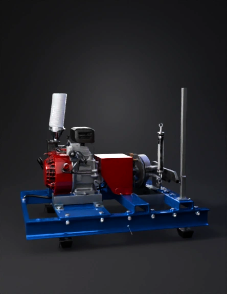
engine dynamometer 3d model
Tags
dynamometer
machine
machine realistic
machine simulation
machine simulation realistic
mechanical
realistic
simulation
simulation realistic
Input
Prompt
Using the provided image of a single-cylinder engine dynamometer test bed, generate an upgraded and enhanced version of the same setup. Retain the original layout, base frame, engine position, brake drum, lever arm, exhaust ducting, and control panel. Replace the existing shaft coupling with a flexible rubber disc coupling, clearly visible between the engine and dynamometer, and add adjustable mounting slots on the base frame for precise shaft alignment. Modify the brake drum by adding evenly spaced drilled ventilation holes to improve cooling during prolonged operation. Upgrade the mechanical brake with improved friction lining material, subtly highlighted on the brake contact surface. Install vibration-damping rubber bushings at the dynamometer lever arm mounting point to stabilize torque and load measurements. The image should be realistic, high-resolution, laboratory-grade equipment, clean industrial environment, accurate mechanical proportions, professional engineering appearance, with optional subtle labels pointing to the upgraded components.
Detailed Info
Related Models
Enter invite code
Enter invite code to get credits!
 jpenglis2000


 jpenglis2000