3D Workspace
Home
Assets
Affiliate Program
Sign up/Log in
?
Upgrade
DCC Bridge
3D Creation Made Simple
Text & Image to 3D Model in seconds
One-Click Texturing & Smart Detail Editing
Free Credits Monthly
Start Free
Anonymous1764825554
12-04 05:25
Model Name
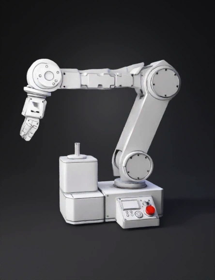
robotic arm 3d model
Tags
machine
rendering
realistic
Input
Prompt
We will draw the arm in isometric 3-D, the easiest engineering drawing style. Everything is built from 3-D boxes, cylinders, and shafts. ✅ STEP 1 — Start with the Base (A 3-D Block) Draw a flat rectangle. From each of the back corners, draw two lines going up and back at a 30° angle. Connect the lines so it becomes a 3-D box (rectangular prism). This is the base platform. ✅ STEP 2 — Draw the Base NEMA 23 Stepper (3-D Cube) A NEMA 23 motor is just a block. Draw a cube sitting on the base: Square front Back edges slanted at the same 30° angles On top of the cube, draw a small cylindrical shaft. This is your base rotation motor. ✅ STEP 3 — Draw the Rotating Joint (Cylinder) On top of the motor shaft, draw a short cylinder: Oval on top Vertical sides Oval on bottom This represents the rotary base joint. ✅ STEP 4 — Draw the Shoulder Motor (Another Cube) On top or slightly to the side (depending on your design), draw another NEMA 23 cube. Draw a shaft sticking out horizontally. This shaft will connect to Arm Segment 1. ✅ STEP 5 — Draw Arm Segment 1 (3-D Beam) Arm segments are just long rectangular prisms. To draw one: Draw a long rectangle. Add the 30° angled edges to the back. Connect the edges so the rectangle becomes a 3-D bar. This is Arm Segment 1. ✅ STEP 6 — Add the Elbow Motor (Another Cube) At the end of Arm Segment 1: Draw a small NEMA-shape cube. Add a small shaft coming out of it. This is the Elbow Motor. ✅ STEP 7 — Draw Arm Segment 2 (Another 3-D Bar) Same as Arm Segment 1, but slightly shorter. Draw a long rectangle extending from the elbow shaft. Give it the same 30° angled edges. Connect to form a 3-D segment. ✅ STEP 8 — Draw the Wrist Servo (Small Box + Circle) At the end of Arm Segment 2: Draw a small rectangular box (servo). On the face of the servo, draw a round circle (servo horn). If you want more detail, add mounting flanges. This is the wrist joint. ✅ STEP 9 — Draw the 130 DC Motor (Rounded Box) Attached to the servo horn: Draw a small rounded rectangular box in 3-D. Add a small shaft coming out. This is the gripper motor. ✅ STEP 10 — Draw the Gripper The simplest 3-D gripper is: Draw a small cylinder or block at the shaft end. From that block, draw two curved jaws or angled claws: <---- ----> Add thickness to make them look 3-D. 📦 STEP 11 — Draw the HMI Panel (3-D Box) On the base, draw a slanted-top box with: A small rectangle for the LCD A cylinder on top for the rotary encoder knob Small circles for LEDs A big mushroom-shaped button for the E-stop A small circle with a dot for the buzzer These do not connect to the arm; they sit beside it. ✅ STEP 1 — Start with the Base (A 3-D Block) Draw a flat rectangle. From each of the back corners, draw two lines going up and back at a 30° angle. Connect the lines so it becomes a 3-D box (rectangular prism). This is the base platform. ✅ STEP 2 — Draw the Base NEMA 23 Stepper (3-D Cube) A NEMA 23 motor is just a block. Draw a cube sitting on the base: Square front Back edges slanted at the same 30° angles On top of the cube, draw a small cylindrical shaft. This is your base rotation motor. ✅ STEP 3 — Draw the Rotating Joint (Cylinder) On top of the motor shaft, draw a short cylinder: Oval on top Vertical sides Oval on bottom This represents the rotary base joint. ✅ STEP 4 — Draw the Shoulder Motor (Another Cube) On top or slightly to the side (depending on your design), draw another NEMA 23 cube. Draw a shaft sticking out horizontally. This shaft will connect to Arm Segment 1. ✅ STEP 5 — Draw Arm Segment 1 (3-D Beam) Arm segments are just long rectangular prisms. To draw one: Draw a long rectangle. Add the 30° angled edges to the back. Connect the edges so the rectangle becomes a 3-D bar. This is Arm Segment 1. ✅ STEP 6 — Add the Elbow Motor (Another Cube) At the end of Arm Segment 1: Draw a small NEMA-shape cube. Add a small shaft coming out of it. This is the Elbow Motor. ✅ STEP 7 — Draw Arm Segment 2 (Another 3-D Bar) Same as Arm Segment 1, but slightly shorter. Draw a long rectangle extending from the elbow shaft. Give it the same 30° angled edges. Connect to form a 3-D segment. ✅ STEP 8 — Draw the Wrist Servo (Small Box + Circle) At the end of Arm Segment 2: Draw a small rectangular box (servo). On the face of the servo, draw a round circle (servo horn). If you want more detail, add mounting flanges. This is the wrist joint. ✅ STEP 9 — Draw the 130 DC Motor (Rounded Box) Attached to the servo horn: Draw a small rounded rectangular box in 3-D. Add a small shaft coming out. This is the gripper motor. ✅ STEP 10 — Draw the Gripper The simplest 3-D gripper is: Draw a small cylinder or block at the shaft end. From that block, draw two curved jaws or angled claws: <---- ----> Add thickness to make them look 3-D. 📦 STEP 11 — Draw the HMI Panel (3-D Box) On the base, draw a slanted-top box with: A small rectangle for the LCD A cylinder on top for the rotary encoder knob Small circles for LEDs A big mushroom-shaped button for the E-stop A small circle with a dot for the buzzer These do not connect to the arm; they sit beside it.
Detailed Info
Related Models
Enter invite code
Enter invite code to get credits!