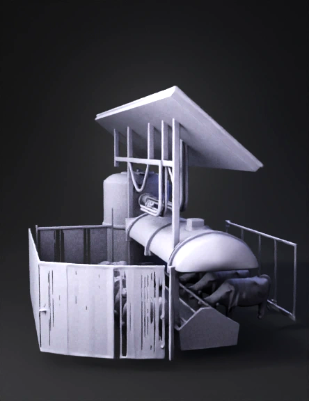
Biodigestor Modelo 3d 3D Model
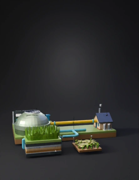
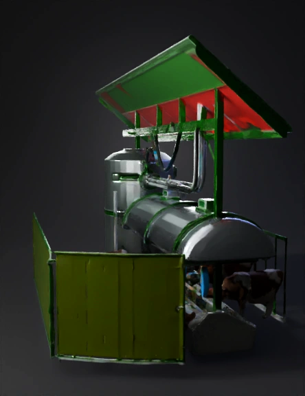
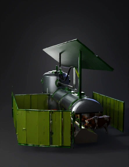
Waste To Farm Diagram 3D Model
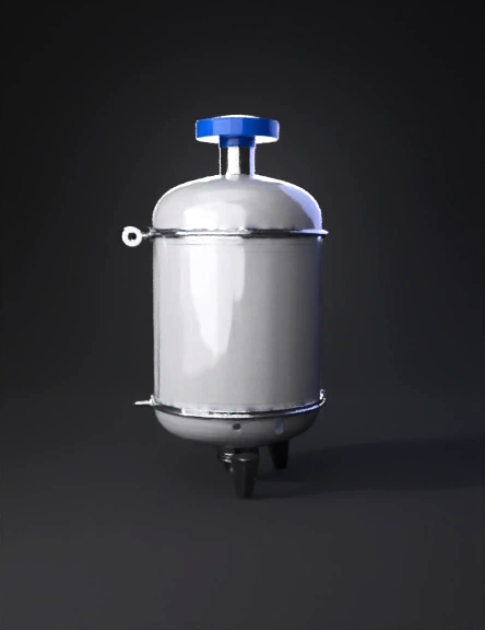
Biogas Tank 3D Model
Biogas Tank 3D Model
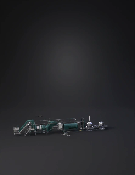
Waste Management System 3D Model

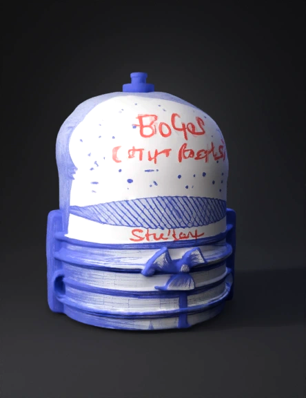
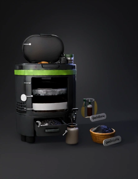
Bio Bin Composter 3D Model
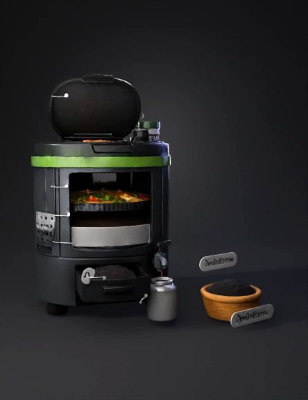
Composting Machine 3D Model
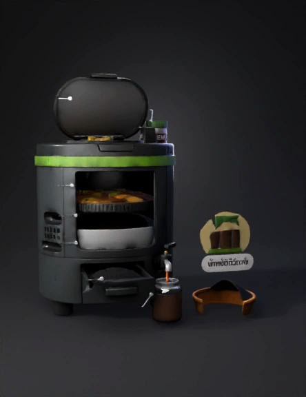
Biobin Smart Composting Machine 3D Model
Kitchen Appliance 3D Model
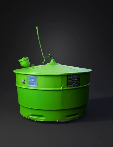
Biogas Digester 3D Model
Biogas Plant 3D Model
Biogas Plant 3D Model
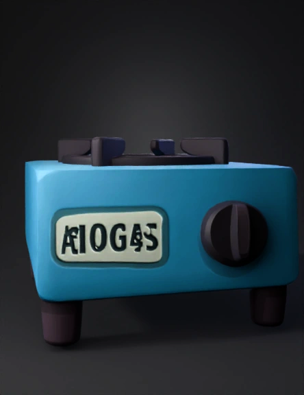
Biogas Stove 3D Model
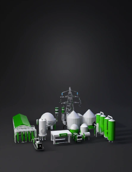
Biofuel Plant 3D Model
Bio Co2 Logo 3D Model
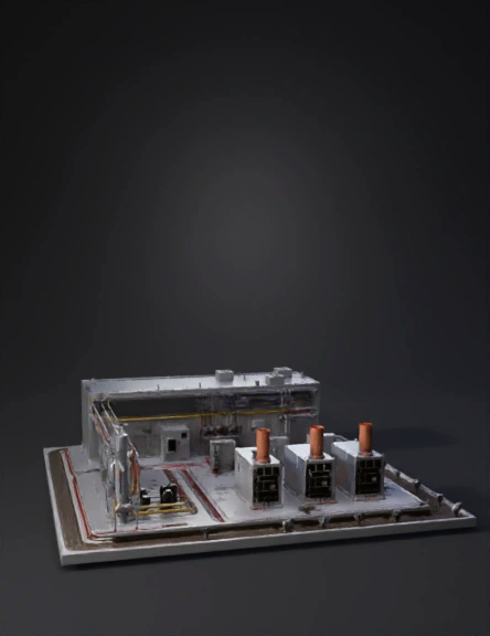
Industrial Facility 3D Model
Gasification Plant 3D Model
Biogas Digester 3D Model