?
Braking 3D Models
Find the best Braking 3D Models, free download in STL, FBX, GLB, OBJ, 3MF, USDZ for 3D modeling and creation in Blender, 3D printing, game developing, animation, eCommerce, AR/VR and etc. Generated by Tripo AI 3D Generator.
You May Also Like :
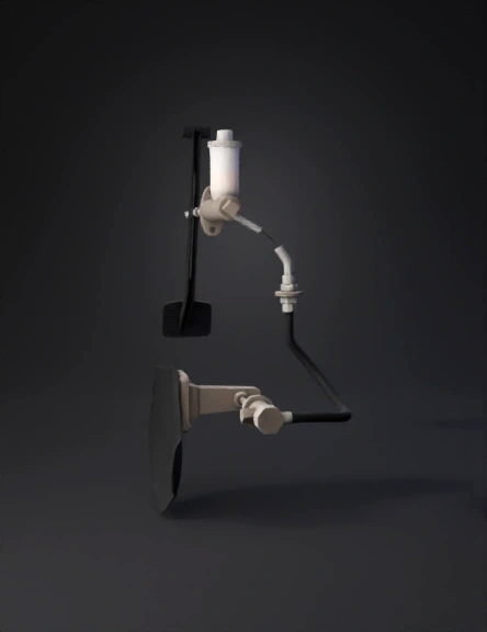
Brake Pedal Assembly 3D Model
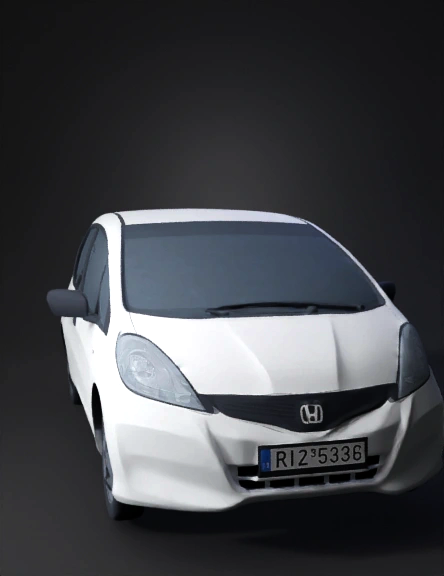
Compact Car 3D Model
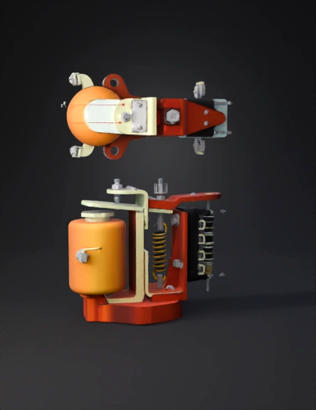
Caster Wheel Brake 3D Model
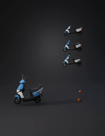
Electric Scooter 3D Model
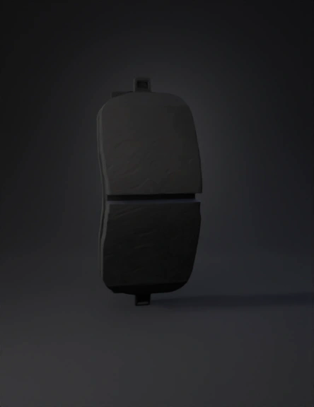
Brake Pad 3D Model
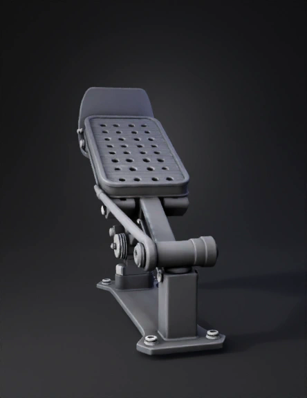
Brake Pedal Assembly 3D Model
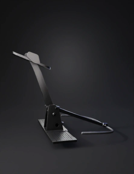
Brake Pedal Assembly 3D Model
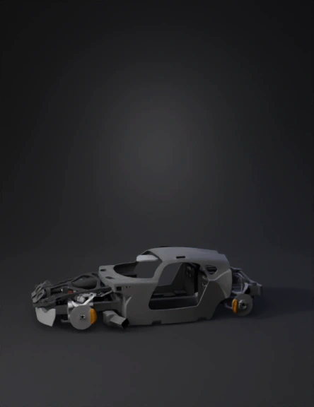
Sports Car Chassis 3D Model
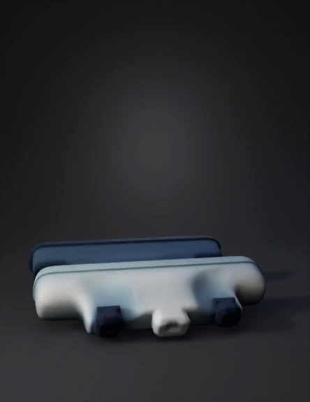
Small Brake Pad 3D Model
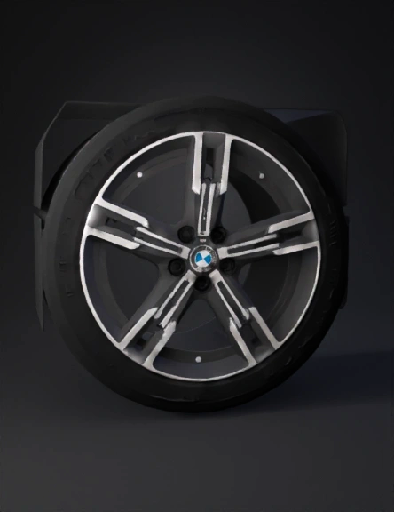
Bmw Alloy Wheel 3D Model
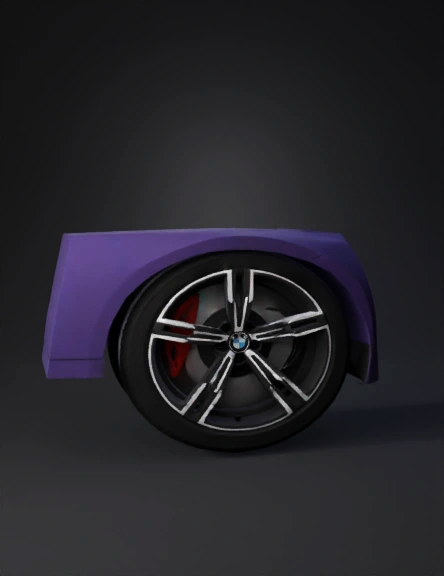
Car Wheel 3D Model
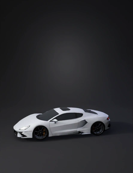
Sports Car 3D Model
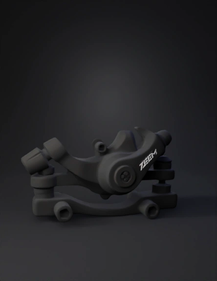
Bicycle Brake Caliper 3D Model
Bicycle Disc Brake 3D Model
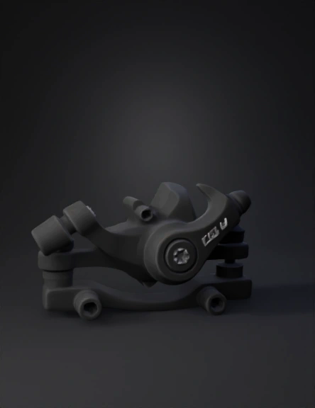
Brake Caliper 3D Model
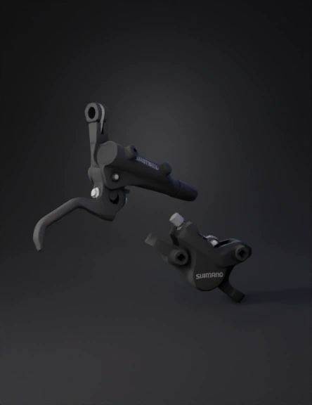
Bicycle Brake Lever 3D Model
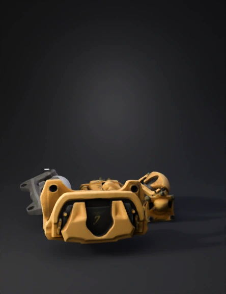
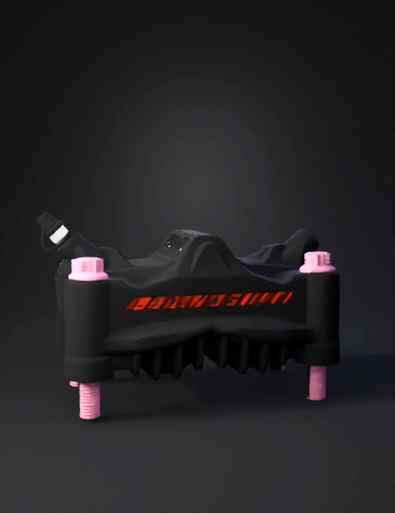
Gold Brake Caliper 3D Model
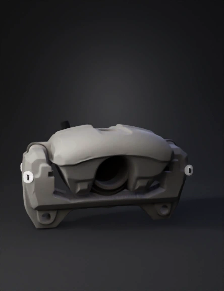
Brake Caliper 3D Model