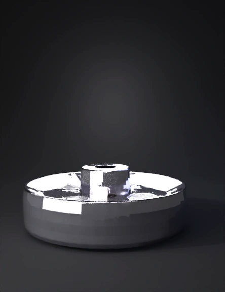
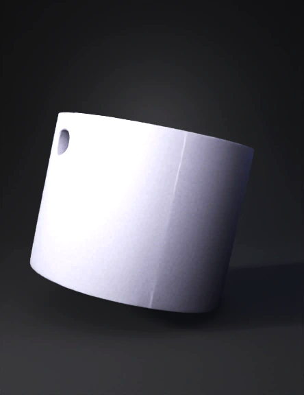
Flange 3D Model
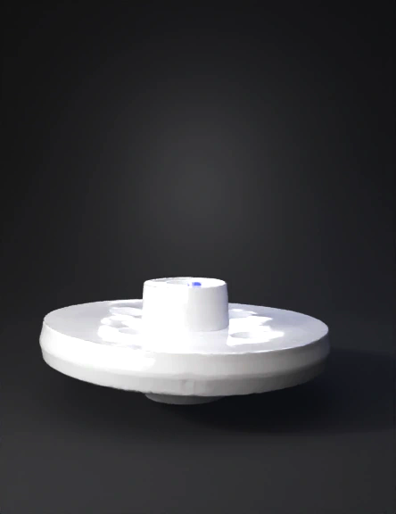
Flange Plate 3D Model
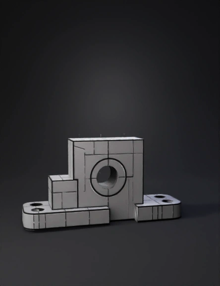
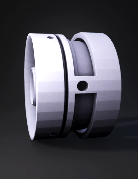
Bearing Housing 3D Model
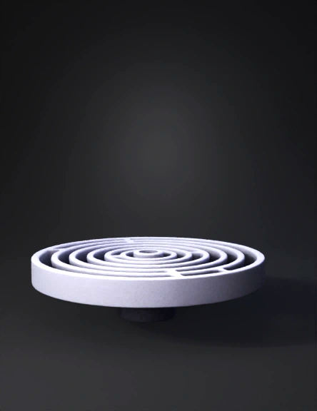
Metal Ring Assembly 3D Model
Red Cylindrical Knob 3D Model
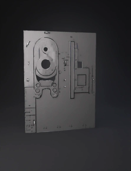
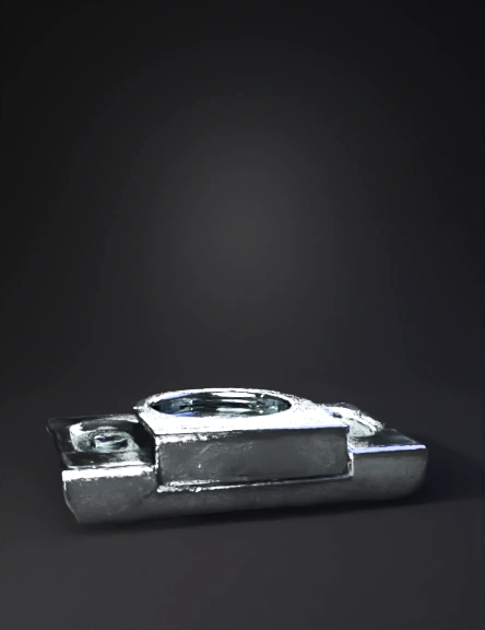
Mounting Bracket 3D Model
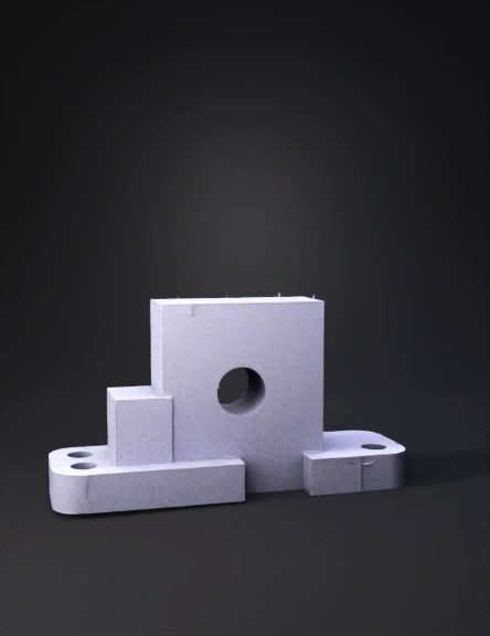
Mounting Bracket 3D Model
Bearing Housing 3D Model
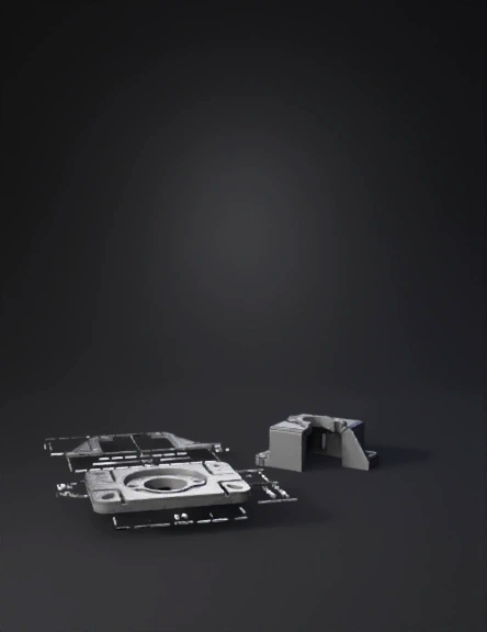
Machined Part 3D Model
Metal Mounting Bracket 3D Model
Mechanical Component 3D Model
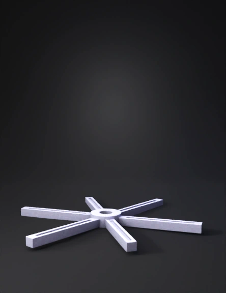
Six-armed Metal Hub 3D Model
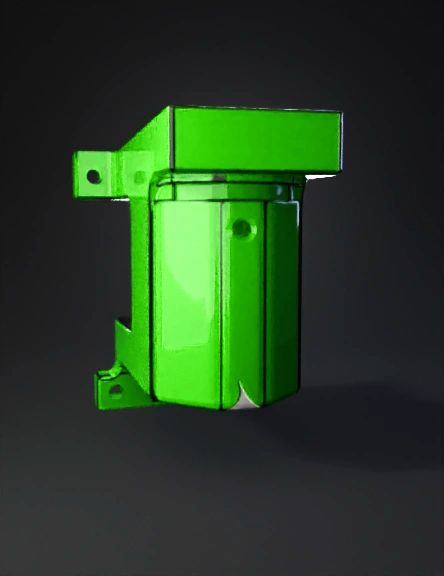
Green Mounting Bracket 3D Model
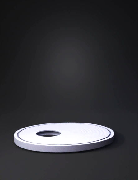
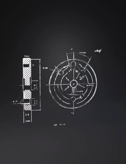
Machined Metal Disc 3D Model
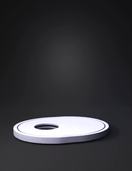
Machined Metal Disc 3D Model
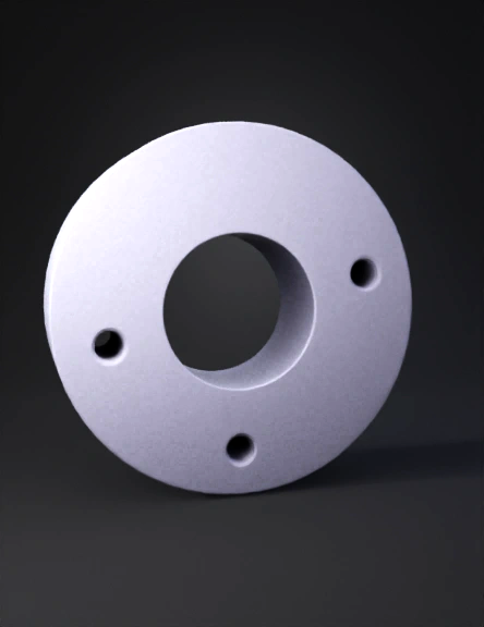
Metal Flange 3D Model
Round Flange 3D Model
Circular Flange 3D Model