?
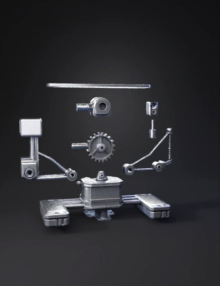
Micro servo 3D Models
Find the best Micro servo 3D Models, free download in STL, FBX, GLB, OBJ, 3MF, USDZ for 3D modeling and creation in Blender, 3D printing, game developing, animation, eCommerce, AR/VR and etc. Generated by Tripo AI 3D Generator.
You May Also Like :
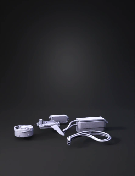
Rc Hobby Parts 3D Model
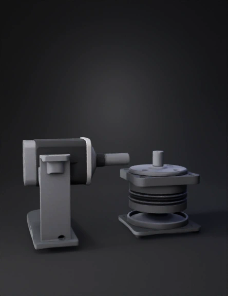
Servo Mounting 3D Model
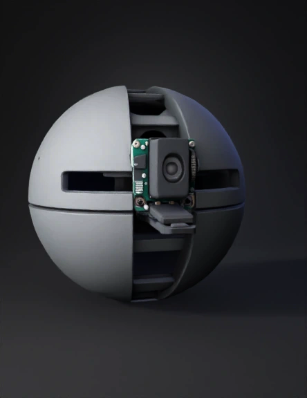
Spherical Robot 3D Model
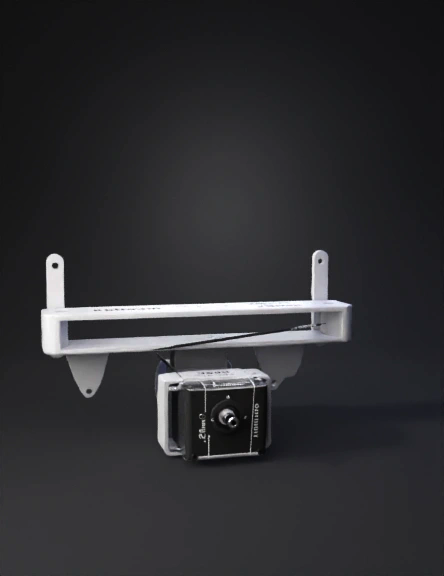
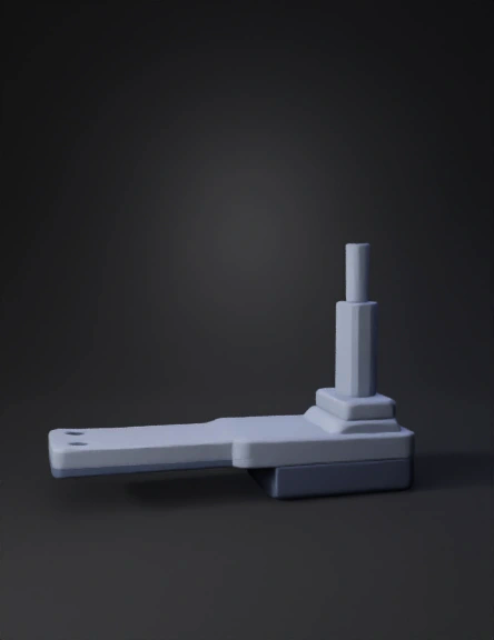
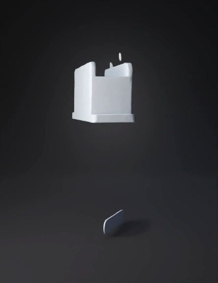
3d Printable Bracket 3D Model
Sorting Arm 3D Model
Arduino Microcontroller 3D Model
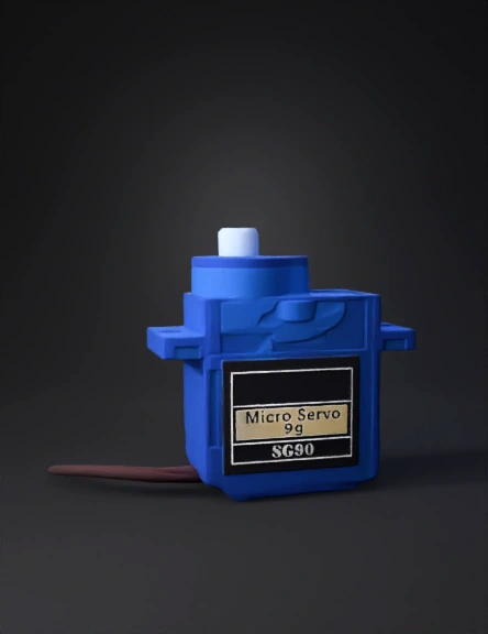
Micro Servo 3D Model
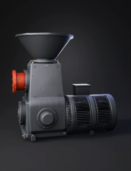
Micropulverizador 3d Modelo 3D Model
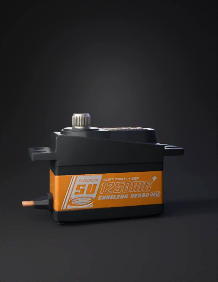
伺服电机3d模型 3D Model
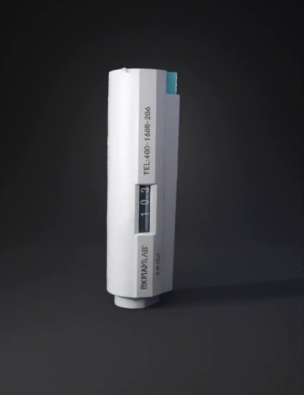
3d 移液器 模型 3D Model
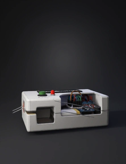
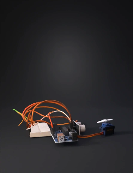
Microcontroller Project 3D Model
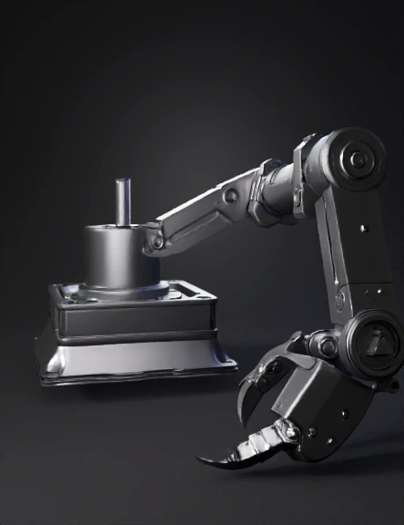
Robotic Arm 3D Model
Robotic Gripper 3D Model
Servo Motor Holder 3D Model
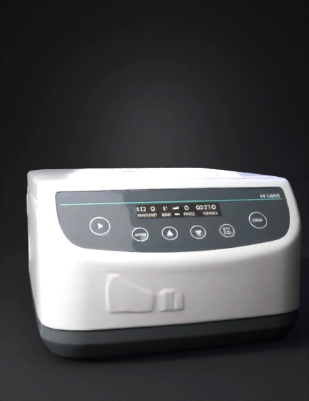
Microcentrifuge 3D Model
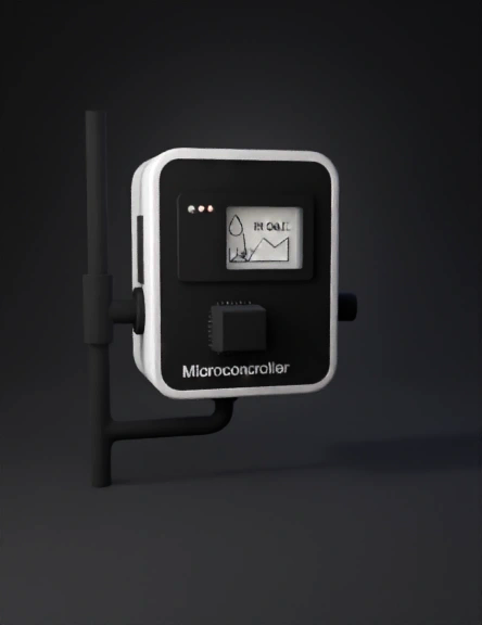
Microcontroller 3D Model
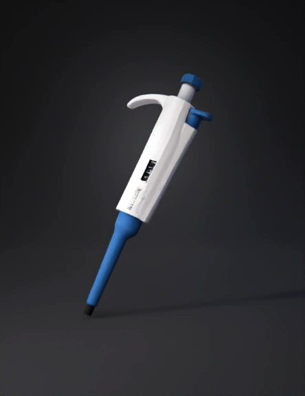
Micropipette 3D Model
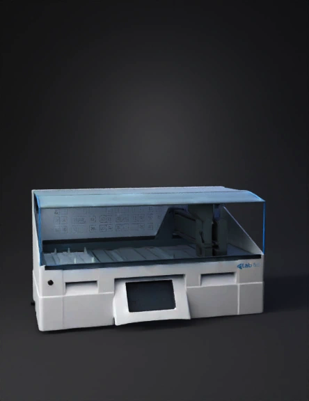
Lab Instrument 3D Model