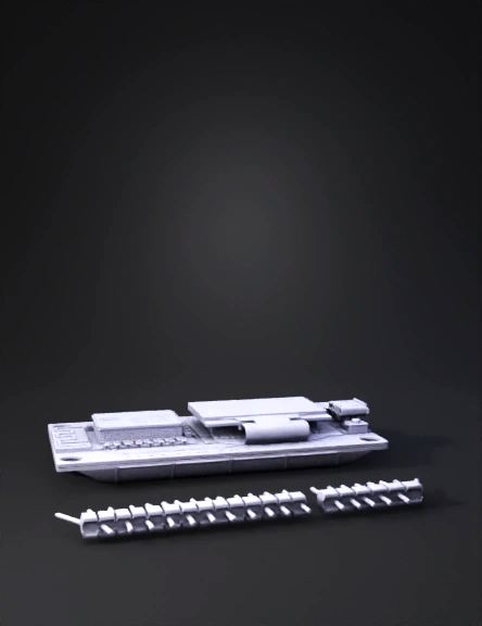
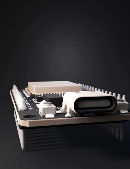
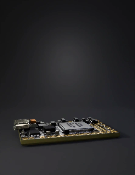
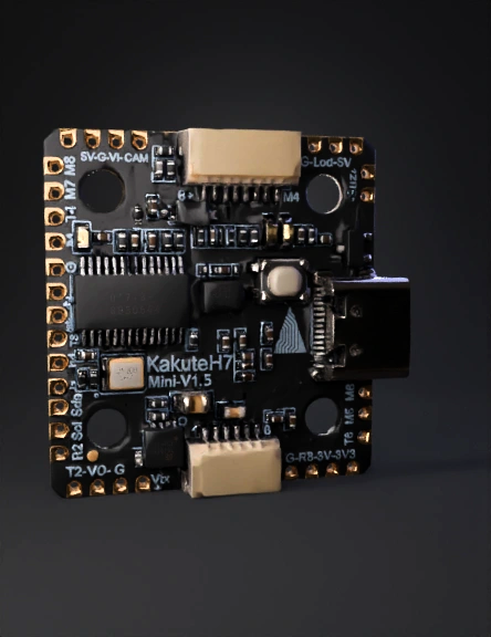
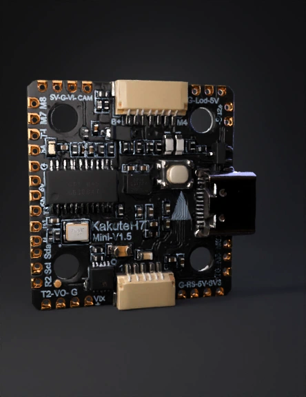
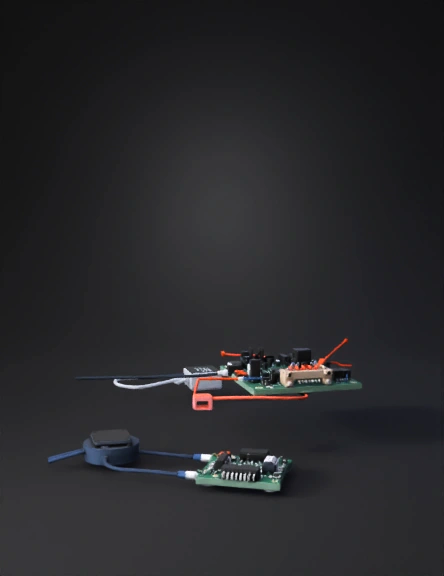
Microcontroller Board 3D Model
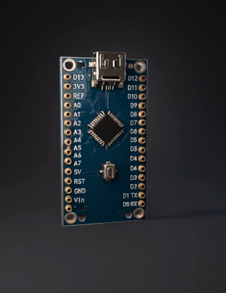
Microcontroller Board 3D Model
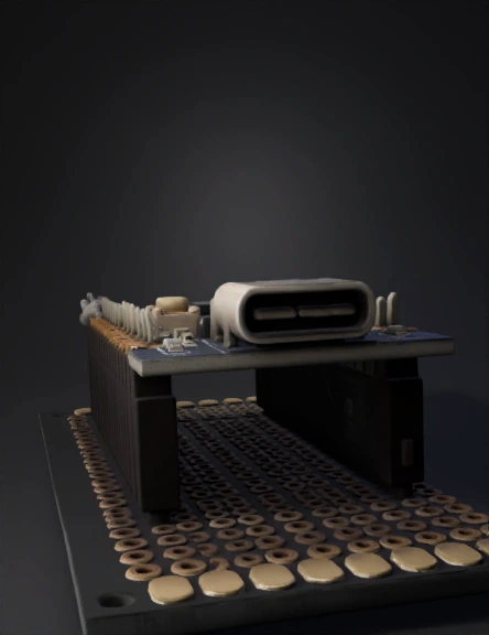
Microcontroller Board 3D Model
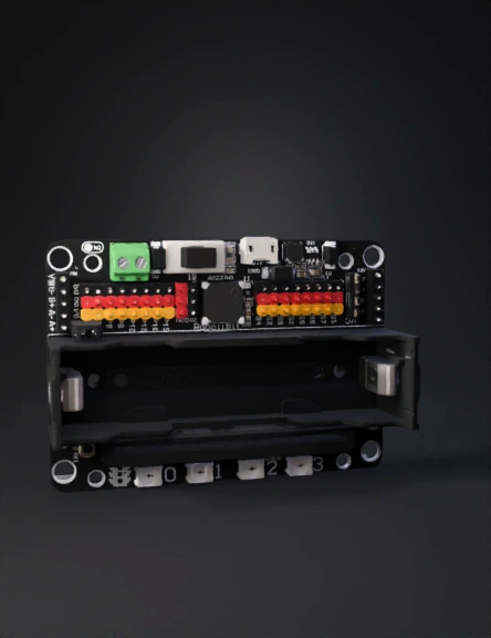
Microcontroller Board 3D Model
Microcontroller Board 3D Model
Microcontroller Board 3D Model
Microcontroller Board 3D Model
Microcontroller Board 3D Model
Microcontroller Board 3D Model

Cnc Router 3D Model
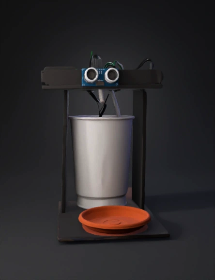
Cup Holder 3D Model
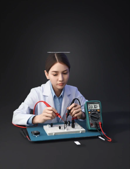
Electronics Lab 3D Model
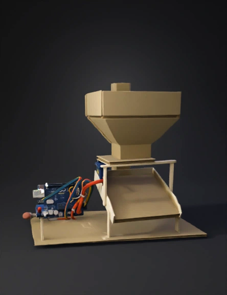
Cardboard Prototype 3D Model
Electronic Circuit Prototype 3D Model
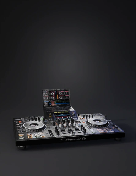
Pioneer Dj Controller 3D Model
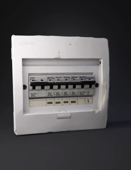
Electrical Panel 3D Model
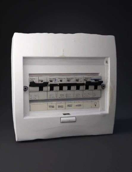
Breaker Panel 3D Model
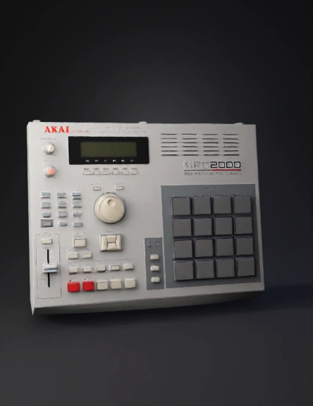
Drum Machine 3D Model