3D Workspace
Home
Assets
Affiliate Program
Creator Program
Sign up/Log in
View Plans
DCC Bridge
Anonymous1775101996
04-13 05:42
Model Name
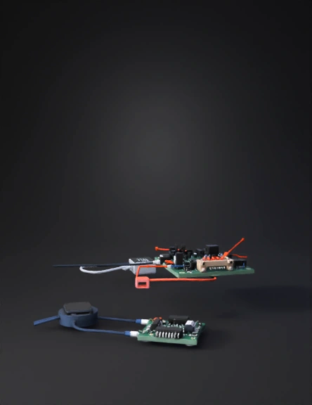
microcontroller board 3d model
Tags
esp32
machine
machine realistic
machine rendering
machine rendering realistic
microcontroller
microcontroller board
realistic
rendering
rendering realistic
sensor module
Prompt
Step 1: Define Your Nets (Power Rails): Create distinct power lines for 5V and 3.3V. Since the ESP32 and LoRa SX1278 operate at 3.3V, ensure they are connected to a regulated 3.3V source to prevent damage. Step 2: Establish the SPI Bus for LoRa: Connect the LoRa SX1278 to the ESP32 using the SPI protocol pins: SCK (GPIO18), MISO (GPIO19), MOSI (GPIO23), and NSS/CS (GPIO5). Step 3: Connect Sensors and GPS: Ultrasonic Sensor: Connect the Trigger and Echo pins to the ESP32. Use a voltage divider on the Echo pin to step down the 5V signal to 3.3V for the ESP32’s safety. GPS Module: Connect the TX/RX pins to the ESP32’s hardware serial pins (GPIO16/17). Step 4: Add Protection and Decoupling: Place 0.1µF and 10µF decoupling capacitors near the power pins of the ESP32 and LoRa module to filter out electrical noise and stabilize signals.
Detailed Info
Related Models
Enter invite code
Enter invite code to get credits!