?
Rotational 3D Models
Find the best Rotational 3D Models, free download in STL, FBX, GLB, OBJ, 3MF, USDZ for 3D modeling and creation in Blender, 3D printing, game developing, animation, eCommerce, AR/VR and etc. Generated by Tripo AI 3D Generator.
You May Also Like :
Rotating Disk 3D Model

Fabric Sculpture 3D Model

Wind-up Airplane 3D Model

Twisted Vase 3D Model
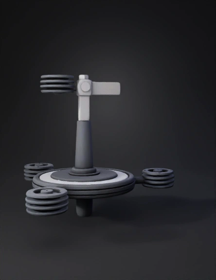
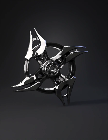
Mechanical Spinner 3D Model
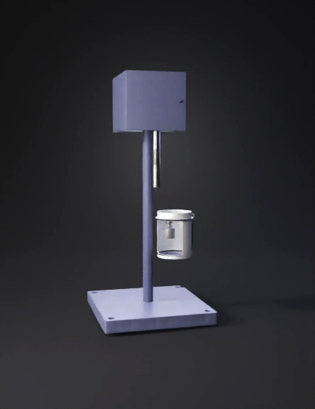
Rotational Viscometer 3D Model
Molecular Model 3D Model
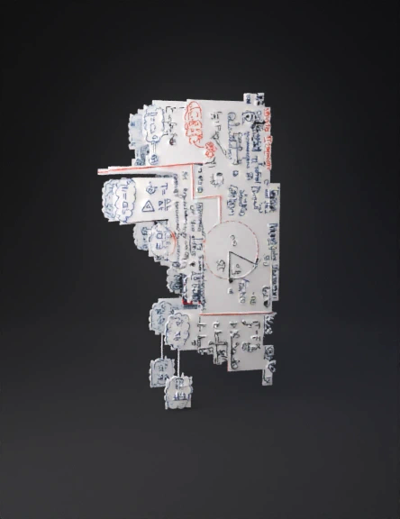
C1_P2_Technisch_bemaßte_Ansicht_T1 3D Model
Rotational Mechanical Component 3D Model

Dodecaedro 3d Modello 3D Model
Joystick Knob 3D Model
Dual-joystick Controller 3D Model
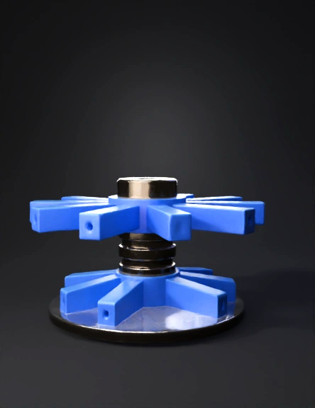
Four-arm Flywheel 3D Model
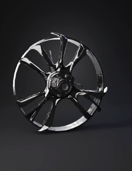
Four-arm Flywheel 3D Model
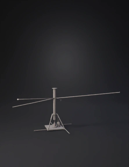
Angular Momentum Diagram 3D Model
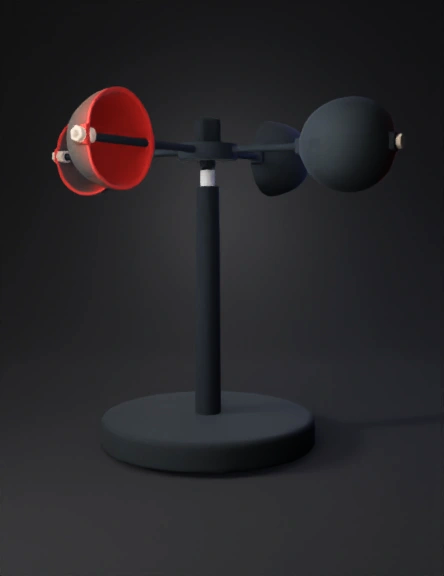
Kinetic Sculpture 3D Model
Rotating Ring Structure 3D Model

Floating Cube 3D Model