3D Workspace
Home
Assets
Affiliate Program
Creator Program
Sign up/Log in
View Plans
DCC Bridge
krisiangelov2009
12-15 17:02
Model Name
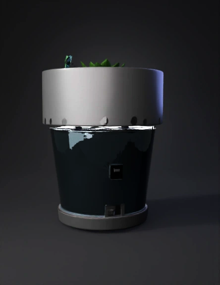
hydroponic planter 3d model
Tags
hydroponic
machine
machine realistic
machine rendering
machine rendering realistic
realistic
rendering
rendering realistic
Prompt
Create a detailed 3D model of a smart plant pot system, based on the provided diagram. The model should clearly show all internal and external components, with precise spaces and mounting points for each electronic and mechanical part. Overall Structure: A two-part pot design: an "Outer Vase Shell" and an "Inner Plant Cup." The inner plant cup should be removable and sit within the outer shell, allowing for a water reservoir below. The outer shell should have an integrated compartment at the bottom for electronics, accessible from the exterior. Internal Components (within the pot/reservoir): Inner Plant Cup: Designed to hold soil and a plant, with drainage holes at the bottom leading to the reservoir. Water Reservoir (Zone B): The space between the inner plant cup and the outer vase shell, designed to hold water. Soil Moisture Sensor: A sensor inserted into the soil of the inner plant cup, with a cable running down into the electronics compartment. Rim Nozzle: A small nozzle positioned at the rim of the inner plant cup, designed to spray water onto the soil. 5V Water Pump: Located at the bottom of the water reservoir, with an inlet tube submerged in the water and an outlet tube (Vinyl Water Tube) connecting to the rim nozzle. Quick-Disconnect Connector: A connector for the water tube, positioned where the tube exits the pot for external connection (e.g., to a larger water source or for easy refilling). Electronics Compartment (Dry Deck - Zone C): This compartment should be sealed off from the water reservoir. ESP32 Microcontroller: A dedicated space and mounting points for the ESP32 board. TP4056 USB-C Charger Module: A specific slot or mounting area for the TP4056 module, with an exposed USB-C Port on the exterior of the pot. MT3608 Voltage Booster: Space and mounting for the voltage booster module. 18650 Rechargeable Battery: A snug compartment for a single 18650 battery cell, with clear terminals for connection to the charging module and power circuits. Power Toggle Switch: A cutout and mounting point for a physical toggle switch on the exterior of the pot. Cabling and Connections: Show realistic pathways and channels for all internal wiring and tubing. Cables from the soil moisture sensor, water pump, and USB-C port should route neatly to the respective electronic modules. The vinyl water tube should run from the pump, up the side of the reservoir, and connect to the rim nozzle. Material Aesthetics: The pot should appear to be made of a durable, matte plastic (e.g., ABS or PLA for 3D printing). The inner components like the pump and electronics should have realistic textures for their materials. Key Design Considerations for the AI: Modularity: The inner plant cup should be easily removable. The electronics compartment cover (not explicitly shown but implied for access) should also be considered. Waterproofing: The electronics compartment must be completely sealed from the water reservoir. Assembly: All components should fit together logically and securely. Scale: The pot should be suitable for a small to medium-sized houseplant. The final 3D model should be clean, functional, and visually representative of a ready-to-manufacture smart pot.
Detailed Info
Related Models
Enter invite code
Enter invite code to get credits!