3D Workspace
Home
Assets
Affiliate Program
Creator Program
Sign up/Log in
View Plans
DCC Bridge
Anonymous1773951132
03-20 16:37
Model Name
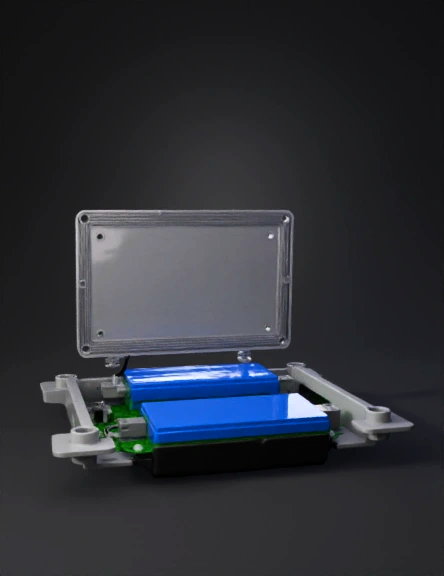
electronics enclosure 3d model
Tags
design
electronics
electronics enclosure
modular
props
props realistic
props rendering
props rendering realistic
realistic
rendering
rendering realistic
Prompt
Design a compact two-piece electronics enclosure made entirely of plain plastic geometry. CRITICAL — READ FIRST: This model contains ONLY plastic parts. No PCBs, no electronic components, no circuits, no solder joints, no chips, no wires, no connectors, no metal parts of any kind are to be modeled or appear anywhere in the scene The colored zones are simply flat colored plastic floor surfaces painted onto the base tray floor — they are just colored rectangles recessed 0.5mm into the floor surface to visually indicate where a real component will be placed later by hand Do not model, imply, or suggest any electronic component in any way. If it has circuits on it, do not include it Overall dimensions: 130mm (L) × 90mm (W) × 50mm (H), wall thickness 2mm, internal corners filleted 1mm, external corners filleted 2mm. Every part is plain grey plastic except the three colored floor zones. BATTERY HOLDER DIMENSIONS — this drives the overall case width: Exact size: 69.85mm (L) × 63.5mm (W) × 19.05mm (H) — converted from 2.75" × 2.5" × 0.75" to be safe, use the maximums Mounts on the exterior bottom face of the base, centered The battery holder sits in a recessed black plastic cradle 1mm deep so it cannot slide around Two wire exit slots cut through the base floor into the case interior — one on the left side of the cradle, one on the right side, each 8mm × 5mm. This is because the positive wire is soldered and splits into two wires inside the case (one to ESP32 VIN, one to PCA9685 V+ terminal block), and the negative wire splits into two wires (one to ESP32 GND, one to PCA9685 GND). The two slots give clean routing for both sides Battery holder retained by 2× M2.5 standoffs through the base floor BASE TRAY INTERIOR — plastic only: Floor has two recessed colored zones, each 0.5mm deep, flat, no detail inside them: Solid blue rectangle — 62.5mm × 25.4mm, along the back wall of the tray interior, centered left-to-right. This is where the PCA9685 will sit. The terminal block end of the PCA9685 faces the LEFT short wall Solid green rectangle — 51mm × 28mm, front-left of the tray interior, with a 6mm grey gap between it and the blue zone. The ESP32 USB port end faces the LEFT short wall. Positioned so the wire gap between green and blue zones runs front-to-back through the middle of the case — this is the wire highway where the split positive and negative wires from the battery travel up through the floor slots and route to both boards Everything outside those two colored rectangles is flat grey plastic floor. WIRE ROUTING LOGIC — reflected in the physical layout: Battery positive wire enters through LEFT floor slot → splits inside case → one wire goes forward-left to green ESP32 zone (VIN), one wire goes back-left to blue PCA9685 zone (V+ terminal) Battery negative wire enters through RIGHT floor slot → splits inside case → one wire goes to ESP32 GND, one wire goes to PCA9685 GND terminal The 6mm gap channel between green and blue zones accommodates these wire runs plus the I2C SDA/SCL wires between the two boards STANDOFFS — plain grey hollow plastic cylinders only: 4× at corners of blue zone, 8mm tall, 4mm outer diameter, 2.5mm inner hole 4× at corners of green zone, 8mm tall, 4mm outer diameter, 2.5mm inner hole 2× on base floor over battery cradle for retention, 3mm tall, 4mm outer diameter, 2.5mm inner hole WALL CUTOUTS — open holes through plastic walls only, nothing inside them: Left short wall: one 12mm × 6mm open slot for USB port access, one 14mm × 6mm open slot above it for power switch Back long wall: one 10mm × 8mm open slot at the left end aligned to the blue PCA9685 zone terminal block end, for power wire access from outside if needed Front long wall: one continuous 65mm × 12mm open slot along the bottom edge aligned to the blue zone, for servo wire connectors to exit forward Base floor: two 8mm × 5mm open slots as described above in battery section, one left side one right side of the cradle LID — separate plain grey plastic part: Flat 2mm thick grey plastic rectangle matching the base footprint 1.5mm interior alignment lip around the perimeter 4× plain M2.5 cylindrical holes in corners 2× rectangular ventilation slots 20mm × 2mm cut through the lid above the blue PCA9685 zone Show the lid floating 15mm above the base as a separate body so both parts are visible simultaneously CHASSIS MOUNTING TABS — plain grey plastic: 4× rectangular tabs 8mm × 10mm extending outward from each base corner Each tab has one plain 2.5mm cylindrical through-hole Tabs are flush with the base bottom face Nothing else. No labels, no text, no logos, no electronic components, no wires, no decorative features. Two plastic parts only: base tray and lid.
Detailed Info
Related Models
Enter invite code
Enter invite code to get credits!