3D Workspace
Home
Assets
Affiliate Program
Creator Program
Sign up/Log in
View Plans
DCC Bridge
Anonymous1773951132
03-20 07:20
Model Name
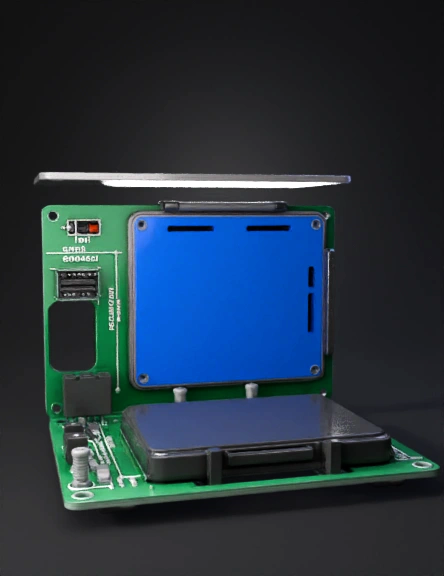
electronics enclosure 3d model
Tags
electronics
electronics enclosure
machine
machine realistic
machine rendering
machine rendering realistic
realistic
rendering
rendering realistic
Prompt
Design a compact two-piece electronics enclosure. Visualization model only — do not prepare for slicing or printing, no supports, no print orientation. Do not add any decorative features, spider legs, servo arms, or themed geometry. Plain mechanical enclosure only. Overall dimensions: 110mm (L) × 80mm (W) × 40mm (H), wall thickness 2mm, internal corners filleted 1mm, external corners filleted 2mm. COMPONENT ZONES — solid filled colored floor surfaces only. Do not model the actual components. Just fill the zone with solid color flush with the base floor so placement is immediately obvious: BLUE zone — PCA9685 servo driver: Exact board dimensions: 62.5mm (L) × 25.4mm (W) Placed along the back long wall of the case interior The 2-pin terminal block is on the LEFT short end of the board — the wall directly beside the terminal block must have a 10mm × 8mm rectangular cutout so power wires from the battery can plug straight into the terminal block from outside the case without opening the lid The servo header pins run along the long edge facing the front of the case — the front long wall must have a wide open slot 65mm × 12mm running along it at header height so all 16 servo wire connectors can plug in and exit forward out of the case 4× M2.5 hollow screw boss standoffs at corners of the blue zone, 8mm tall, plain grey GREEN zone — ESP32 development board: Exact board dimensions: 51mm (L) × 28mm (W) Placed along the front left area of the case interior, beside the PCA9685 but oriented so its USB port faces the left short wall Left short wall must have a 12mm × 6mm rectangular cutout aligned to the ESP32 USB port so it can be reprogrammed without opening the case Same left wall: one additional 14mm × 6mm slot above or below the USB cutout for an inline slide power switch on the battery positive wire 4× M2.5 hollow screw boss standoffs at corners of the green zone, 8mm tall, plain grey BLACK zone — 4×AA battery holder: Standard 4×AA holder dimensions: 62mm (L) × 30mm (W) × 15mm (H) Mounts flush underneath the base on the exterior bottom face Enclosed with a solid black 2mm bottom cover plate — not exposed One 12mm × 8mm slot on the short side of the battery tray so power wires exit upward through the base floor into the case interior toward the terminal block and ESP32 VIN pin Battery holder retained by 2× M2.5 screw holes through the base floor into the holder Grey — all remaining geometry: walls, lid, base floor outside the colored zones, corner tabs Wire routing: 6mm gap between the green ESP32 zone and blue PCA9685 zone for I2C wire routing (SDA/SCL) Open channel in the base floor beneath both boards for wire management Lid: Flat grey lid 2mm thick, shown as a separate body floating 15mm above the base so both pieces are clearly visible simultaneously Interior alignment lip 1.5mm tall that drops inside the base walls 4× M2.5 screw holes in corners 2× ventilation slots 20mm × 2mm on the side above the PCA9685 blue zone Chassis mounting: 4× plain grey corner tabs extending 8mm outward from base corners, each with one M2.5 through-hole for bolting onto a robot chassis
Detailed Info
Related Models
Enter invite code
Enter invite code to get credits!