Sistema De Monitoramento 3d 3D Model
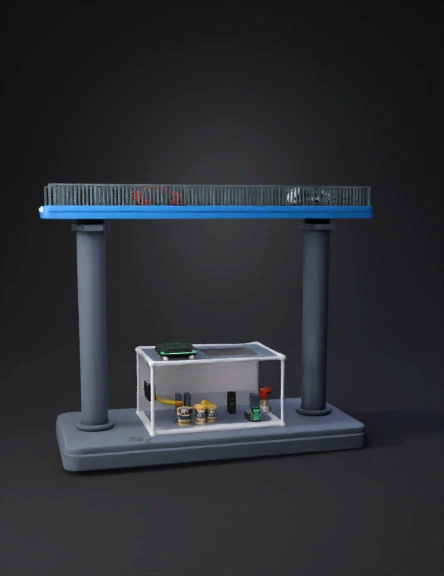
Bridge Health Monitor 3D Model
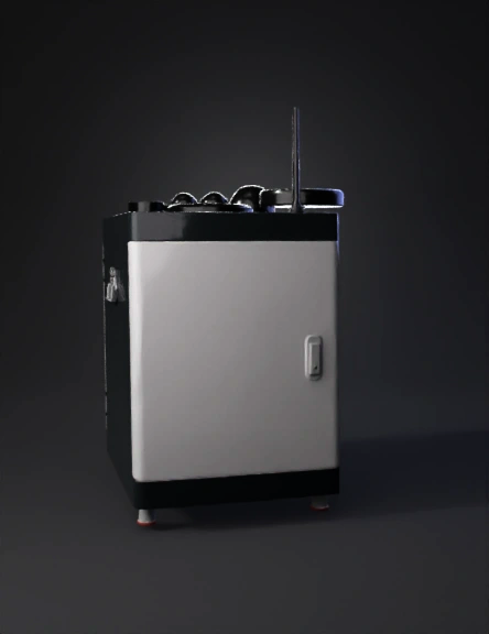
Environmental Monitor 3D Model
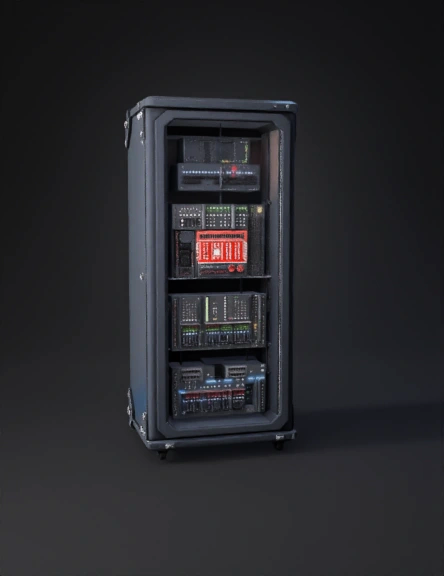
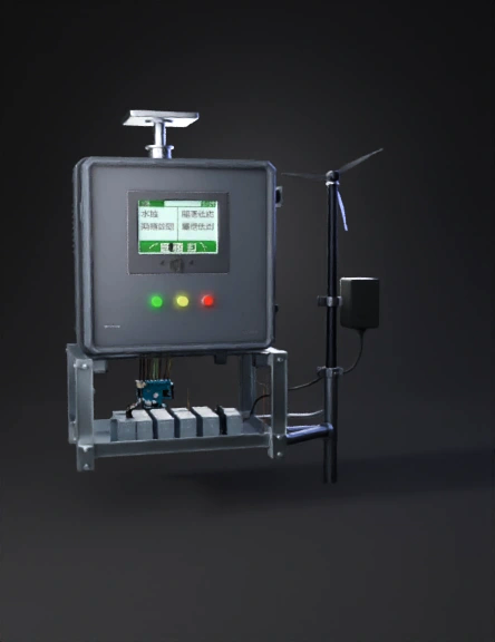
监控系统柜 3d模型 3D Model
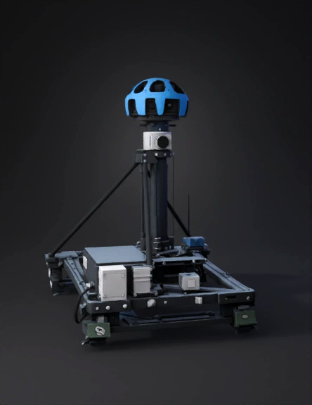
Lidar Scanner 3D Model
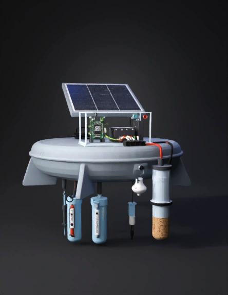
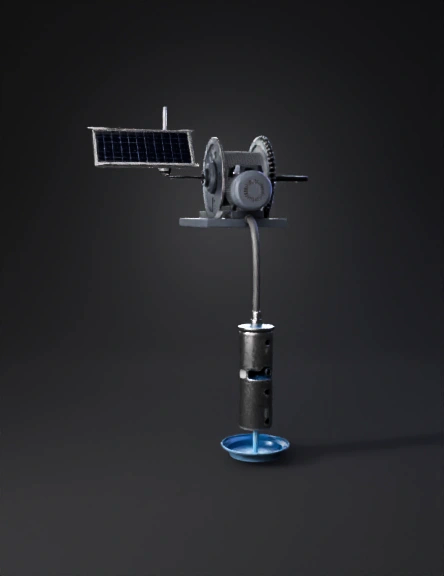
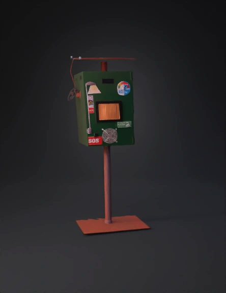
Solar Powered Monitoring Device 3D Model
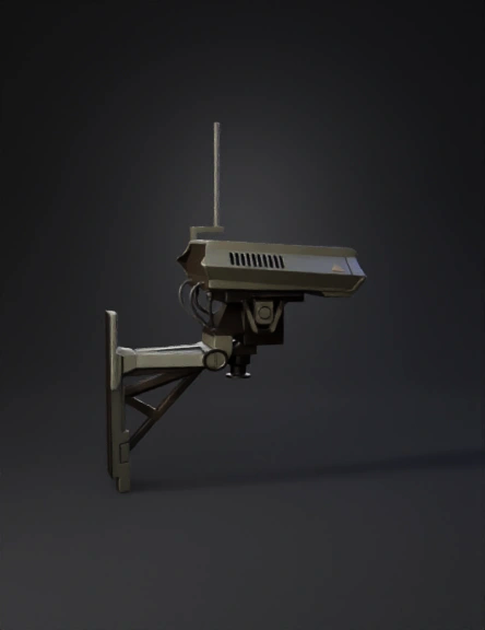
Surveillance Camera 3D Model
Coastal Flood System 3D Model
Air Quality Monitor 3D Model
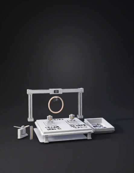
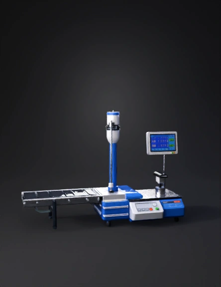
Multi-station 3d Inspection Model 3D Model
3d Inspection Station 3D Model
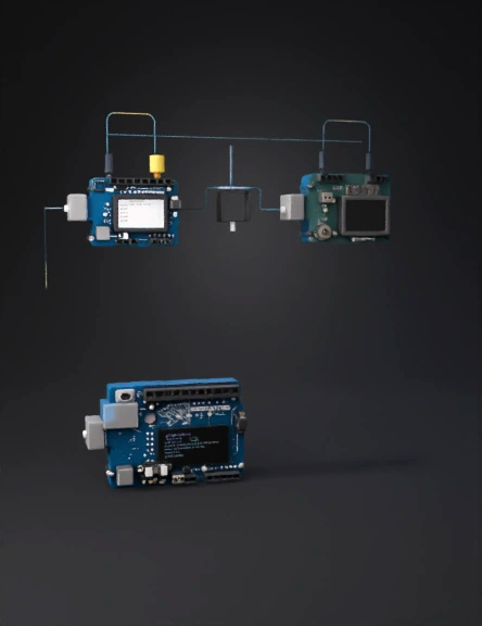
Arduino Security System 3D Model
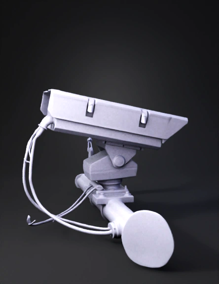
Surveillance Camera 3D Model
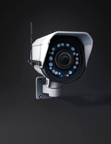
Security Camera 3D Model
3d Модель Автоматизированной Системы 3D Model
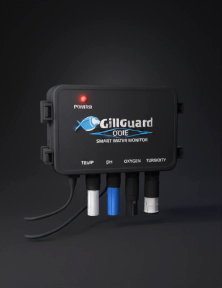
Water Monitor 3D Model
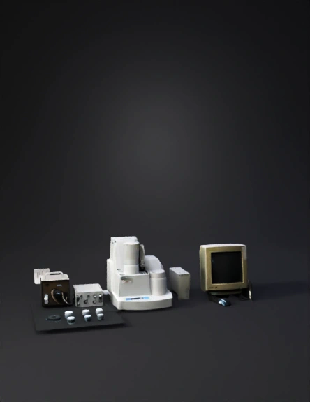
Lab Equipment 3D Model
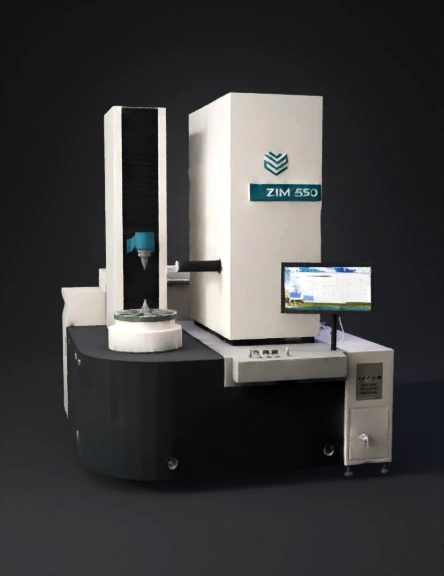
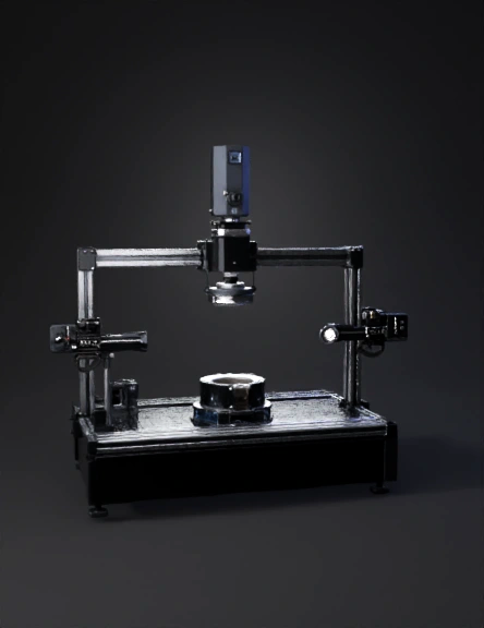
Coordinate Measuring Machine 3D Model