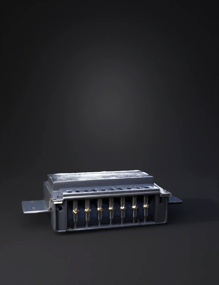
data connector 3d model
1. Overall Bounding Box (Outer Dimensions)To block out the primary volume of the component:Total Height (Z-axis): 2.87 ± 0.20 mm. Total Width (X-axis at the base): 11.85 ± 0.20 mm. Total Depth/Length (Y-axis): 15.20 mm. 2. Metal Shell & Housing StructureTop Shell Width: 11.40 ± 0.25 mm. Main Shell Body Length: 9.70 mm (Reference dimension). Front Opening Width: 7.70 ± 0.20 mm across the top entry lip , tapering out to the full 11.85 mm base width. Shell Side Tabs: The metal shell has side mounting tabs that extend slightly; the total distance across the centers of the front mounting pads is 11.85 mm. 3. Pin Configuration & SpacingData Contacts: There are 8 main data contacts. Contact Pitch (Spacing): 1.10 ± 0.10 mm between each of the 8 pins. Pin Width: The physical width of the contact pins at the mating edge is 0.30 mm , while the recommended PCB landing pad width for these pins is 0.70 mm. 4. Materials & Sub-componentsIf you are rendering the model with distinct materials
4K·PBR·v3.1-20260211


